Injection Molded Ferrite
Ferrite powder in a thermoplastic binder, molded to shape — thin walls and complex geometry in a single step; the polymer matrix lowers flux density.
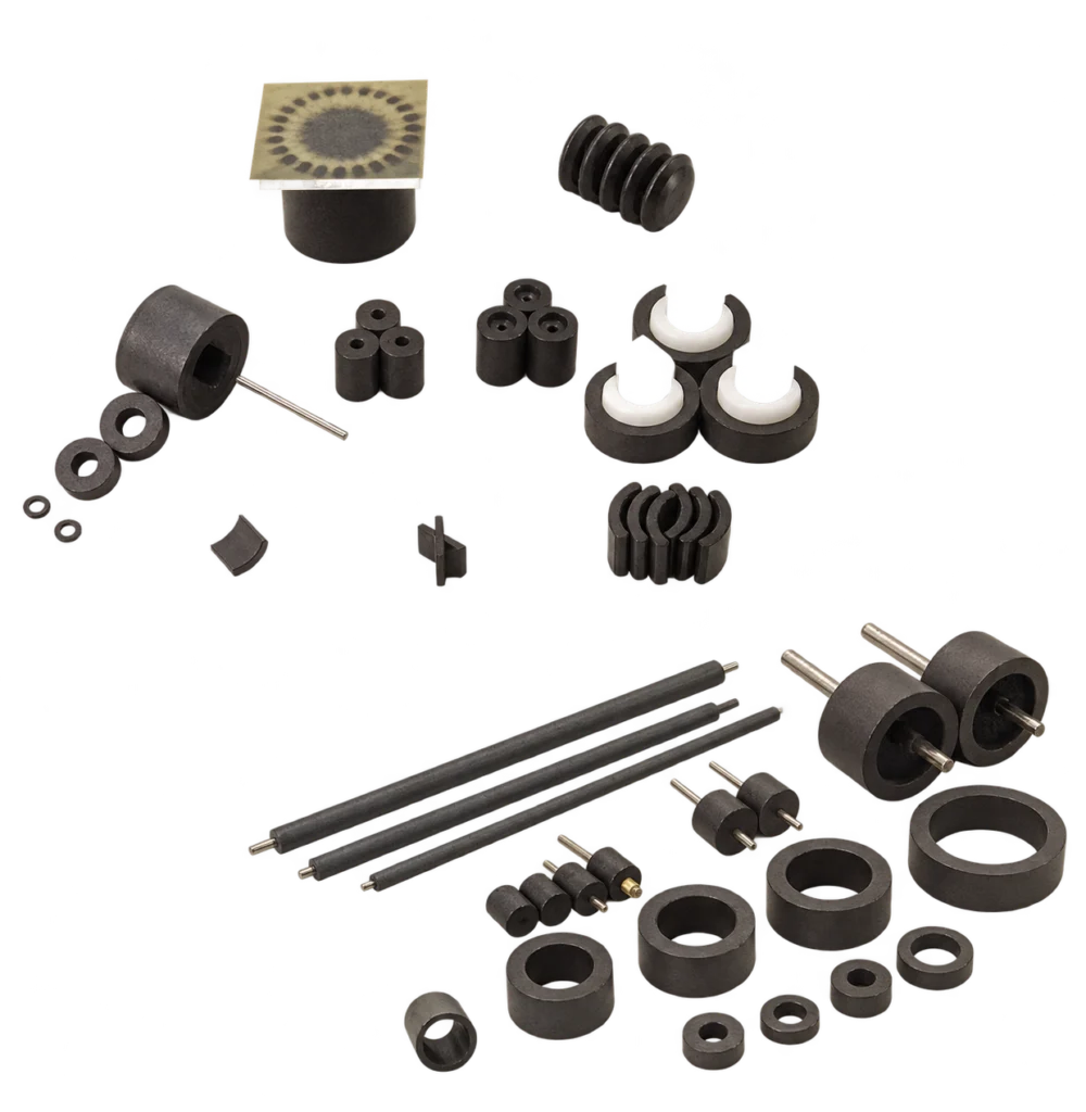
Injection molded ferrite is a bonded magnet route: ferrite magnetic powder is compounded with thermoplastic binders such as PA6 (Nylon 6), PA12 (Nylon 12) or PPS and injected directly into complex dimensional tooling. The magnet is formed to shape in the mold rather than compacted from powder and finished by grinding.
How the part is formed
- The ferrite powder is compounded into a thermoplastic pellet, so the magnetic material reaches the machine already mixed with its binder.
- The steel mold sets the geometry: thin walls, ribs, bosses, bores and pockets come out of the cavity, not off a machining centre.
- A shaft, bushing or bracket can be placed in the tool so the magnet is molded around it, turning two parts and a glue joint into one component.
- The part is magnetized after molding in a fixture that sets the pole pattern, and normally needs no coating.
Where the design calls for maximum flux inside a fixed envelope, the same drawing is reviewed against wet pressed or dry pressed ferrite instead: those routes carry more magnetic material per unit volume, at the cost of the geometry described on this page.
Core Process Characteristics
The material this route works in, the advantage that decides it, the limitation to plan around, and the parts it is normally specified for.
| Primary Material | Hard Ferrite (Ceramic) Magnets |
|---|---|
| Core Advantage |
|
| Key Limitation |
|
| Typical Applications |
|
Process Characteristics
The parameters recorded for this route, each with the note that says how it is confirmed on a project.
| Primary Material | Strontium ferrite powder in a thermoplastic compound A bonded ferrite route rather than a sintered one. |
|---|---|
| Binder Type | PA6, PA12 or PPS The binder and compound grade are selected against the operating temperature, chemical exposure and part design, and confirmed for each project. |
| Forming Method | Injection molding into a steel mold The cavity sets the geometry and the dimensional precision the part holds. |
| Forming Capability | Complex shape in a single molding step Ribs, bosses, bores, pockets and undercuts are formed by the tool rather than added by a second operation. |
| Wall Thickness | Thin-wall sections formed by the mold The minimum wall follows the flow length, the binder and the part design, and is confirmed during tooling review against the drawing. |
| Insert Molding | Shafts, bushings and brackets can be molded in Insert retention and interface strength are confirmed for the assembly. |
| Surface Treatment | Normally none required The binder encapsulates the ferrite particles, so the part is not plated; a specific chemical, outdoor or wash-down environment is confirmed per project. |
| Operating Temperature | -40 °C to 130 °C Range for the listed binder systems; the actual magnet temperature and application conditions are confirmed for the project. |
| Magnetic Orientation | Isotropic or anisotropic, depending on the compound An anisotropic compound is oriented while the part is molded; the final magnetization direction and pole pattern remain a separate requirement, evaluated against the formulation, part and magnetizing fixture. |
| Magnetization Options | Multipole, radial-oriented multipole — confirmed per project Suited to sensor and small motor designs; the pole pattern is evaluated against the formulation, part and magnetizing fixture. |
| Flux Density | Lower than sintered ferrite The polymer matrix dilutes the magnetic volume fraction; that is the trade-off accepted for the geometry. |
| Tolerances | Held by the tool, confirmed per drawing Tolerance the mold holds directly; any dimension that still needs machining is agreed on the drawing. |
| Typical Shapes | Rings, thin-wall cylinders, arcs, blocks and integrated assemblies Whether thin sections are feasible is checked per grade and drawing. |
Technical Documents
-
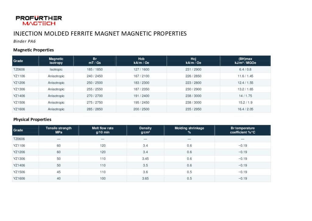 Injection Molded Ferrite Properties — PA6 / PA12 / PPS (PDF) Compound data for the three binder systems this route names — PA6, PA12 and PPS — with each compound's grade designation and its magnetic and physical values, inside the -40 °C to 130 °C window the route is stated for. These grade values appear nowhere else on the site: the route page says only that flux density is lower than sintered ferrite, so a compound has to be shortlisted from this table before tooling is quoted.Select the preview to open the document in a new tab.
Magnetization on This Route
Orientation and magnetization are not the same step: orientation is set while the part is formed or compacted, magnetization is applied afterwards, and what a part can take depends on the material, the tooling and the geometry. Describe the direction, the pole pattern and the face the poles have to sit on — or send the part or its drawing and we will read it with you.
Magnetization feasibility depends on the material, manufacturing process, geometry and required pole pattern. Send us your drawing, sample or magnetization diagram for evaluation.
Explore Magnetization Directions & Pole Patterns → · Magnetization directions and pole patterns explained → · Send the drawing or a sample →
This manufacturing route is worked in the following material line:
Geometries whose own page names this route. A shape that is not listed does not name this route yet, which says the route is not stated for it - not that the geometry cannot be made this way.
Technical notes and selection articles that reference this route.
- How to Specify Magnetization on a Drawing Technical Guide
How to describe magnetization …
Planning a Part on This Route?
Send the drawing, the sample or the operating conditions you work from. We review the route against the part and answer with the tooling, tolerance and feasibility questions it raises.