



Through-thickness Magnetization
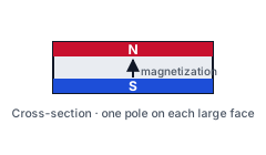
Magnetization runs across the thickness of the part, with one pole on each large face.
Custom sintered, compression molded and injection molded NdFeB magnets for motors, sensors and industrial equipment.
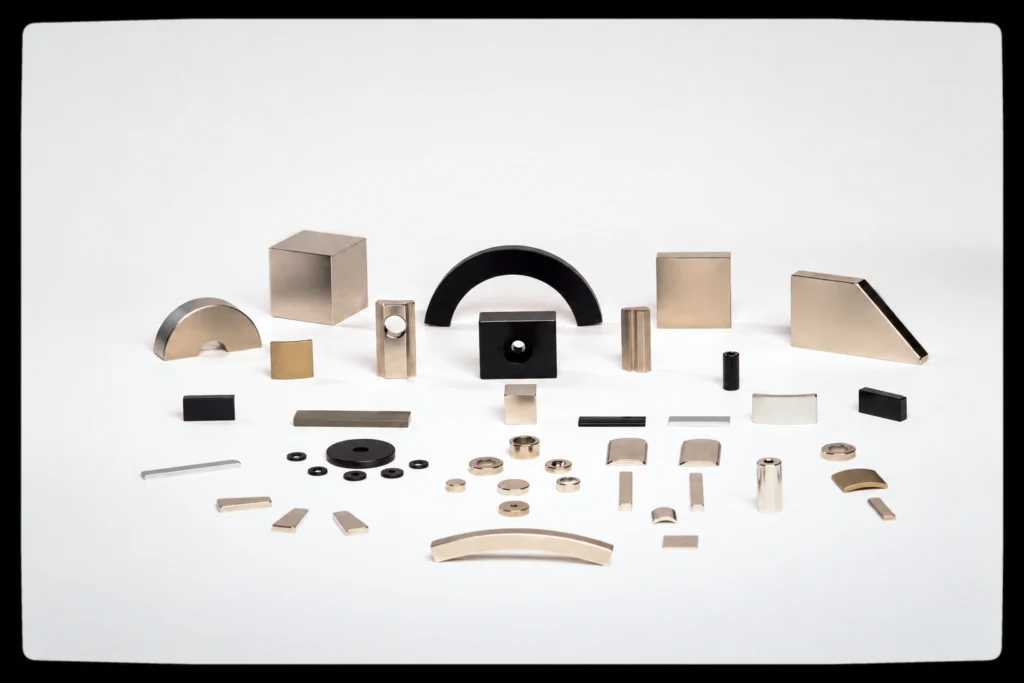
NdFeB magnets offer high magnetic performance for compact designs. This range covers three manufacturing routes: sintered, compression molded and injection molded. Compression molded and injection molded NdFeB belong to the bonded magnet family; sintered NdFeB is a separate route. The bonded NdFeB materials presented here are isotropic and are available through compression molding and injection molding.
Sintered NdFeB is often selected when magnetic output per unit volume is the priority. Bonded routes offer different possibilities for molded geometry, dimensional control and pole patterns. The suitable route depends on the drawing, magnetic requirements, operating environment and order quantity.
ProfurtherMag coordinates requirements, manufacturing-route selection, sampling and order follow-up with selected partner factories. A project can start from a drawing or an existing sample, even when the specification is not yet complete.
How this material is produced, controlled and supplied: partner-factory manufacturing model, quality and project control, and commercial and shipping.
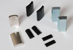
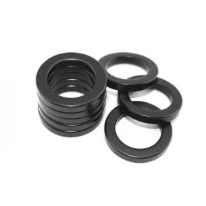
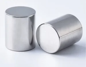
Common shapes include blocks, discs, rings, cylinders, arc segments and countersunk parts. Custom geometry, tooling and achievable tolerances are evaluated for the selected manufacturing route.
Discuss the Shape You NeedCompare the routes below, then send your drawing or sample for evaluation. The selected route and material grade are specified in the quotation.
| Manufacturing Route | Typical Fit | Key Considerations |
|---|---|---|
| Sintered NdFeB | Compact motors, actuators and other parts where magnetic output per unit volume is critical. The listed grades span Br 1020–1470 mT from the N series to the AH series, with operating ceilings from 80 °C (N) to 230 °C (AH). | Brittle material; machining, surface protection and assembly support need evaluation. Magnetization must be compatible with the material orientation. Surface protection is not optional on this route: the listed finishes run 4–65 µm thick, zinc and nickel at 4–20 µm and epoxy at 15–65 µm. |
| Compression Molded NdFeB | Molded rings and other suitable geometries where dimensional consistency and specified pole patterns are important. | Magnetic output is generally lower than sintered NdFeB: the listed band is Br 300–830 mT, so the same flux needs more volume than a sintered part. Geometry, tooling, binder, surface protection and operating temperature must be evaluated. |
| Injection Molded NdFeB | Complex molded geometries and designs that may benefit from integration with other components. | Magnetic output depends on powder loading and material formulation; the listed band is Br 400–630 mT. Thermoplastic binder systems commonly include PA6 (Nylon 6), PA12 (Nylon 12) and PPS; the selected binder, mold design, shrinkage and operating conditions are evaluated for each project. |
Compression molded and injection molded NdFeB are both bonded magnets: magnetic powder is combined with a polymer binder and formed using different molding processes.
Explore common magnetization directions and pole patterns, including axial, diametric, radial and multipole configurations.
Red = N pole Blue = S pole
Magnetization runs across the thickness of the part, with one pole on each large face.
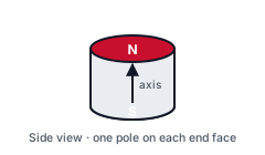
Magnetization runs along the axis, so one end face is N and the other is S.
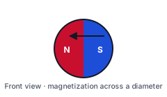
Magnetization runs across a diameter, with the two poles on opposite sides of the part.
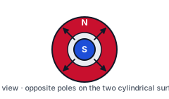
Magnetization runs from the centre outward: one pole on the outer surface, the other at the bore. Which one is N depends on the specification.
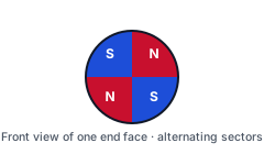
Alternating N and S sectors on one end face, the arrangement used in sensor rotors and small motor rotors.
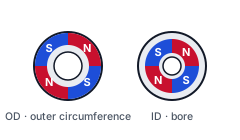
Alternating N and S segments around the outer circumference, around the bore, or around both.
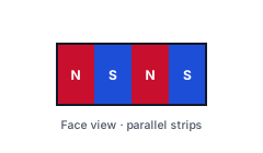
Parallel N and S strips across a face; the strip pitch follows the magnetizing fixture.
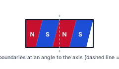
Pole boundaries run at an angle to the axis instead of straight along it; the angle is set by the magnetizing fixture.
Illustrations show magnetization directions and pole patterns. Feasibility depends on the material, grade, geometry and magnetizing tooling, and is confirmed for each project.
Send us your drawing, sample or required pole pattern for evaluation.
Discuss Your Magnetization RequirementsThis is a route-level overview, not a grade specification sheet. Grade-specific magnetic data and physical properties are confirmed for the selected material.
| Material System | Neodymium-Iron-Boron (NdFeB) rare-earth permanent magnet material. |
|---|---|
| Production Routes | Sintered NdFeB · Compression molded NdFeB · Injection molded NdFeB |
| Magnetic Orientation | Sintered: set during magnetic-field pressing. Compression molded and injection molded: isotropic for the materials described on this site. |
| Magnetization Pattern | Direction, pole pattern, pole count and pole location are confirmed per project; the bonded routes are magnetized after molding. |
| Listed Grades | Sintered: N, M, H, SH, UH, EH and AH series · Compression molded: PMC-1 – PMC-13 · Injection molded: NBI-4, NBI-6, NBI-6M, NBI-8 |
| Remanence (Br) | Sintered: 1020 – 1470 mT · Compression molded: 300 – 830 mT · Injection molded: 400 – 630 mT |
| Magnetic Properties | Br, Hcb, Hcj and (BH)max are specified by material grade. |
| Operating Temperature | Sintered: 80 °C (N series) to 230 °C (AH series), confirmed for the selected grade and magnetic circuit; bonded routes also depend on the binder system. |
| Dimensions & Tolerances | Confirmed from the drawing, manufacturing route and inspection requirements. |
| Surface Protection | Selected by route and exposure. Sintered NdFeB commonly requires corrosion protection; bonded parts require material- and environment-specific evaluation. |
The following grade tables apply to sintered NdFeB only. They do not apply to compression molded or injection molded NdFeB. Values are material grade specifications at the stated test conditions, not batch inspection results. Confirm the selected grade and final product requirements for each project.
| Grade | Br mT (kGs) | HcB kA/m (kOe) | HcJ kA/m (kOe) | (BH)max kJ/m³ (MGOe) | Max. operating temperature (°C) |
|---|---|---|---|---|---|
| N35 | 1170–1220 (11.7–12.2) | ≥868 (≥10.9) | ≥955 (≥12) | 263–287 (33–36) | 80 |
| N38 | 1220–1250 (12.2–12.5) | ≥899 (≥11.3) | ≥955 (≥12) | 287–310 (36–39) | 80 |
| N40 | 1250–1280 (12.5–12.8) | ≥907 (≥11.4) | ≥955 (≥12) | 302–326 (38–41) | 80 |
| N42 | 1280–1320 (12.8–13.2) | ≥923 (≥11.6) | ≥955 (≥12) | 318–342 (40–43) | 80 |
| N45 | 1320–1360 (13.2–13.6) | ≥907 (≥11.4) | ≥955 (≥12) | 342–366 (43–46) | 80 |
| N48 | 1360–1400 (13.6–14.0) | ≥892 (≥11.2) | ≥955 (≥12) | 366–390 (46–49) | 80 |
| N50 | 1400–1420 (14.0–14.2) | ≥836 (≥10.5) | ≥955 (≥12) | 382–406 (48–51) | 80 |
| N52 | 1420–1450 (14.2–14.5) | ≥796 (≥10) | ≥955 (≥12) | 398–422 (50–53) | 80 |
| N54 | 1450–1470 (14.5–14.7) | ≥796 (≥10) | ≥955 (≥12) | 414–438 (52–55) | 80 |
| N55 | >1470 (>14.7) | ≥796 (≥10) | ≥876 (≥11) | 422–446 (53–56) | 80 |
| Grade | Br mT (kGs) | HcB kA/m (kOe) | HcJ kA/m (kOe) | (BH)max kJ/m³ (MGOe) | Max. operating temperature (°C) |
|---|---|---|---|---|---|
| 35M | 1170–1220 (11.7–12.2) | ≥868 (≥10.9) | ≥1114 (≥14) | 263–287 (33–36) | 100 |
| 38M | 1220–1250 (12.2–12.5) | ≥899 (≥11.3) | ≥1114 (≥14) | 287–310 (36–39) | 100 |
| 40M | 1250–1280 (12.5–12.8) | ≥923 (≥11.6) | ≥1114 (≥14) | 302–326 (38–41) | 100 |
| 42M | 1280–1320 (12.8–13.2) | ≥955 (≥12.0) | ≥1114 (≥14) | 318–342 (40–43) | 100 |
| 45M | 1320–1360 (13.2–13.6) | ≥995 (≥12.5) | ≥1114 (≥14) | 342–366 (43–46) | 100 |
| 48M | 1360–1400 (13.6–14.0) | ≥1027 (≥12.9) | ≥1114 (≥14) | 366–390 (46–49) | 100 |
| 50M | 1400–1420 (14.0–14.2) | ≥1035 (≥13.0) | ≥1114 (≥14) | 382–406 (48–51) | 100 |
| 52M | 1420–1450 (14.2–14.5) | ≥1035 (≥13.0) | ≥1114 (≥14) | 398–422 (50–53) | 100 |
| 54M | 1450–1470 (14.5–14.7) | ≥1035 (≥13.0) | ≥1114 (≥14) | 414–438 (52–55) | 100 |
| Grade | Br mT (kGs) | HcB kA/m (kOe) | HcJ kA/m (kOe) | (BH)max kJ/m³ (MGOe) | Max. operating temperature (°C) |
|---|---|---|---|---|---|
| 35H | 1170–1220 (11.7–12.2) | ≥868 (≥10.9) | ≥1353 (≥17) | 263–287 (33–36) | 120 |
| 38H | 1220–1250 (12.2–12.5) | ≥899 (≥11.3) | ≥1353 (≥17) | 287–310 (36–39) | 120 |
| 40H | 1250–1280 (12.5–12.8) | ≥923 (≥11.6) | ≥1353 (≥17) | 302–326 (38–41) | 120 |
| 42H | 1280–1320 (12.8–13.2) | ≥955 (≥12.0) | ≥1353 (≥17) | 318–342 (40–43) | 120 |
| 45H | 1320–1360 (13.2–13.6) | ≥971 (≥12.2) | ≥1353 (≥17) | 342–366 (43–46) | 120 |
| 48H | 1360–1400 (13.6–14.0) | ≥1019 (≥12.8) | ≥1353 (≥17) | 366–390 (46–49) | 120 |
| 50H | 1400–1420 (14.0–14.2) | ≥1019 (≥12.8) | ≥1353 (≥17) | 382–406 (48–51) | 120 |
| 52H | 1420–1450 (14.2–14.5) | ≥1019 (≥12.8) | ≥1353 (≥17) | 398–422 (50–53) | 120 |
| 54H | 1450–1470 (14.5–14.7) | ≥1019 (≥12.8) | ≥1353 (≥17) | 414–438 (52–55) | 120 |
| Grade | Br mT (kGs) | HcB kA/m (kOe) | HcJ kA/m (kOe) | (BH)max kJ/m³ (MGOe) | Max. operating temperature (°C) |
|---|---|---|---|---|---|
| 35SH | 1170–1220 (11.7–12.2) | ≥876 (≥11.0) | ≥1592 (≥20) | 263–287 (33–36) | 150 |
| 38SH | 1220–1250 (12.2–12.5) | ≥907 (≥11.4) | ≥1592 (≥20) | 287–310 (36–39) | 150 |
| 40SH | 1250–1280 (12.5–12.8) | ≥939 (≥11.8) | ≥1592 (≥20) | 302–326 (38–41) | 150 |
| 42SH | 1280–1320 (12.8–13.2) | ≥971 (≥12.2) | ≥1592 (≥20) | 318–342 (40–43) | 150 |
| 45SH | 1320–1360 (13.2–13.6) | ≥987 (≥12.4) | ≥1592 (≥20) | 342–366 (43–46) | 150 |
| 48SH | 1360–1400 (13.6–14.0) | ≥995 (≥12.5) | ≥1592 (≥20) | 366–390 (46–49) | 150 |
| 50SH | 1400–1420 (14.0–14.2) | ≥995 (≥12.5) | ≥1592 (≥20) | 382–406 (48–51) | 150 |
| 52SH | 1420–1450 (14.2–14.5) | ≥987 (≥12.4) | ≥1592 (≥20) | 398–422 (50–53) | 150 |
| 54SH | 1450–1470 (14.5–14.7) | ≥995 (≥12.5) | ≥1592 (≥20) | 414–438 (52–55) | 150 |
| Grade | Br mT (kGs) | HcB kA/m (kOe) | HcJ kA/m (kOe) | (BH)max kJ/m³ (MGOe) | Max. operating temperature (°C) |
|---|---|---|---|---|---|
| 30UH | 1080–1130 (10.8–11.3) | ≥812 (≥10.2) | ≥1990 (≥25) | 223–247 (28–31) | 180 |
| 33UH | 1130–1170 (11.3–11.7) | ≥852 (≥10.7) | ≥1990 (≥25) | 247–271 (31–34) | 180 |
| 35UH | 1170–1220 (11.7–12.2) | ≥860 (≥10.8) | ≥1990 (≥25) | 263–287 (33–36) | 180 |
| 38UH | 1220–1250 (12.2–12.5) | ≥876 (≥11.0) | ≥1990 (≥25) | 287–310 (36–39) | 180 |
| 40UH | 1250–1280 (12.5–12.8) | ≥915 (≥11.5) | ≥1990 (≥25) | 302–326 (38–41) | 180 |
| 42UH | 1280–1320 (12.8–13.2) | ≥963 (≥12.1) | ≥1990 (≥25) | 318–342 (40–43) | 180 |
| 45UH | 1320–1360 (13.2–13.6) | ≥971 (≥12.2) | ≥1990 (≥25) | 342–366 (43–46) | 180 |
| 48UH | 1360–1400 (13.6–14.0) | ≥987 (≥12.4) | ≥1990 (≥25) | 366–390 (46–49) | 180 |
| 50UH | 1400–1420 (14.0–14.2) | ≥971 (≥12.2) | ≥1990 (≥25) | 382–406 (48–51) | 180 |
| 52UH | 1420–1450 (14.2–14.5) | ≥971 (≥12.2) | ≥1990 (≥25) | 398–422 (50–53) | 180 |
| Grade | Br mT (kGs) | HcB kA/m (kOe) | HcJ kA/m (kOe) | (BH)max kJ/m³ (MGOe) | Max. operating temperature (°C) |
|---|---|---|---|---|---|
| 28EH | 1020–1080 (10.2–10.8) | ≥780 (≥9.8) | ≥2388 (≥30) | 207–231 (26–29) | 200 |
| 30EH | 1080–1130 (10.8–11.3) | ≥812 (≥10.2) | ≥2388 (≥30) | 223–247 (28–31) | 200 |
| 33EH | 1130–1170 (11.3–11.7) | ≥836 (≥10.5) | ≥2388 (≥30) | 247–271 (31–34) | 200 |
| 35EH | 1170–1220 (11.7–12.2) | ≥860 (≥10.8) | ≥2388 (≥30) | 263–287 (33–36) | 200 |
| 38EH | 1220–1250 (12.2–12.5) | ≥915 (≥11.5) | ≥2388 (≥30) | 287–310 (36–39) | 200 |
| 40EH | 1250–1280 (12.5–12.8) | ≥939 (≥11.8) | ≥2388 (≥30) | 302–326 (38–41) | 200 |
| 42EH | 1280–1320 (12.8–13.2) | ≥955 (≥12.0) | ≥2388 (≥30) | 318–342 (40–43) | 200 |
| 45EH | 1320–1360 (13.2–13.6) | ≥971 (≥12.2) | ≥2388 (≥30) | 342–366 (43–46) | 200 |
| 48EH | 1360–1400 (13.6–14.0) | ≥971 (≥12.2) | ≥2388 (≥30) | 366–390 (46–49) | 200 |
| 50EH | 1400–1420 (14.0–14.2) | ≥971 (≥12.2) | ≥2388 (≥30) | 382–406 (48–51) | 200 |
| Grade | Br mT (kGs) | HcB kA/m (kOe) | HcJ kA/m (kOe) | (BH)max kJ/m³ (MGOe) | Max. operating temperature (°C) |
|---|---|---|---|---|---|
| 28AH | 1020–1080 (10.2–10.8) | ≥780 (≥9.8) | ≥2786 (≥35) | 207–231 (26–29) | 230 |
| 30AH | 1080–1130 (10.8–11.3) | ≥812 (≥10.2) | ≥2786 (≥35) | 223–247 (28–31) | 230 |
| 33AH | 1130–1170 (11.3–11.7) | ≥852 (≥10.7) | ≥2786 (≥35) | 247–271 (31–34) | 230 |
| 35AH | 1170–1220 (11.7–12.2) | ≥876 (≥11.0) | ≥2786 (≥35) | 263–287 (33–36) | 230 |
| 38AH | 1220–1250 (12.2–12.5) | ≥907 (≥11.4) | ≥2786 (≥35) | 287–310 (36–39) | 230 |
| 40AH | 1250–1280 (12.5–12.8) | ≥907 (≥11.4) | ≥2786 (≥35) | 302–326 (38–41) | 230 |
| 42AH | 1280–1320 (12.8–13.2) | ≥907 (≥11.4) | ≥2786 (≥35) | 318–342 (40–43) | 230 |
| 45AH | 1320–1360 (13.2–13.6) | ≥907 (≥11.4) | ≥2786 (≥35) | 342–366 (43–46) | 230 |
General reference values for sintered NdFeB only. These are not batch test results or guaranteed values for every grade.
| Property | Symbol | Unit | Value | Notes |
|---|---|---|---|---|
| Density | ρ | g/cm³ | 7.40–7.80 | |
| Vickers hardness | HV | 550–650 | ||
| Electrical resistivity | μΩ·m | 1.4 | ||
| Compressive strength | MPa | 1050 | ||
| Tensile strength | MPa | 80 | ||
| Bending strength | MPa | 290 | ||
| Thermal conductivity | W/(m·K) | 6–8 | ||
| Coefficient of thermal expansion | 10⁻⁶/K | C⊥: −1.5; C∥: 6.5 | C⊥ and C∥ are the perpendicular and parallel directions; the reference axis, the temperature interval and the test conditions are confirmed for design use. |
Reference coating options for sintered NdFeB. Final coating structure, thickness and appearance are subject to the agreed product specification.
| Coating / process | Abbreviation | Color | Thickness (µm) |
|---|---|---|---|
| Nickel (barrel) | NiCuNi | Bright silver | 5–20 |
| Nickel (rack) | NiCuNi | Bright silver | 5–20 |
| Cr³⁺ zinc (barrel) | Zn | Blue & white | 4–15 |
| Cr³⁺ zinc (rack) | Zn | Blue & white | 4–15 |
| Cr³⁺ color zinc (barrel) | Colored Zn | Bright color | 4–15 |
| Cr³⁺ color zinc (rack) | Colored Zn | Bright color | 4–15 |
| Nickel + black nickel | Black Ni | Black | 5–20 |
| Epoxy | Epoxy | Black | 15–65 |
Compression molded reference grades are listed on the Compression Molded NdFeB route page. Injection molded grade data are confirmed separately for the selected powder and thermoplastic binder system. Datasheets below cover sintered NdFeB grades and their test conditions.
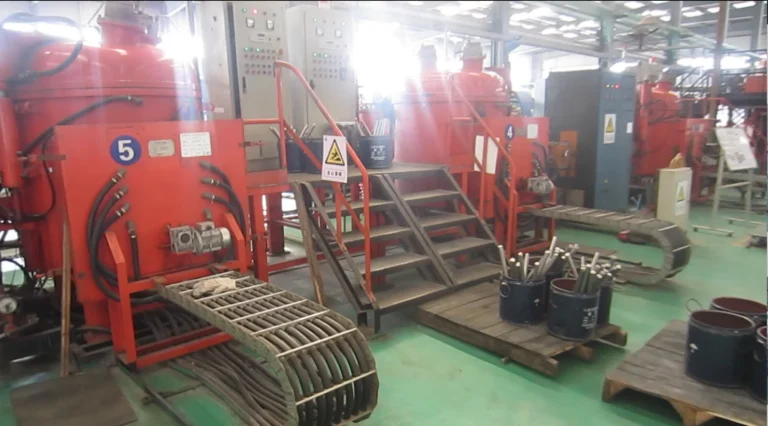
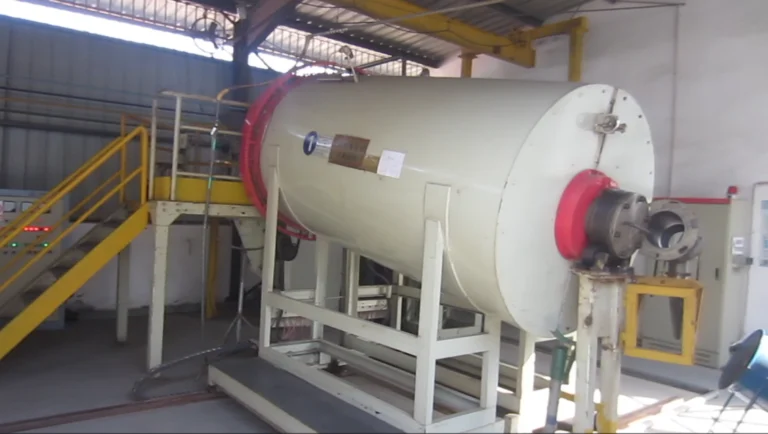
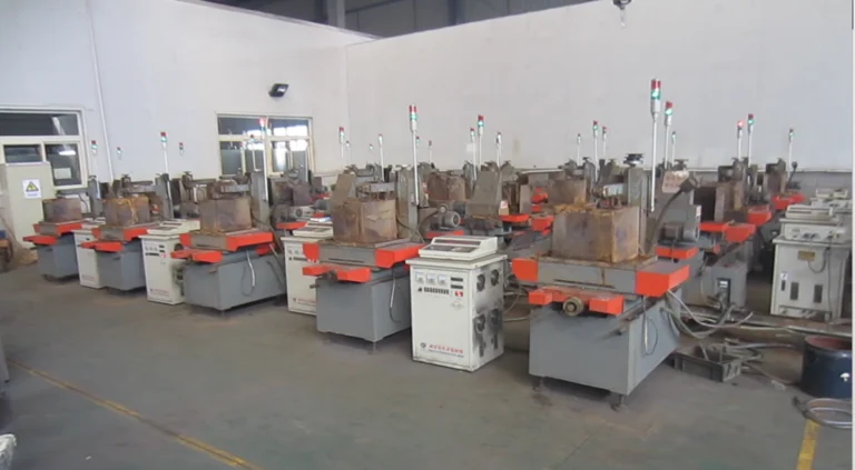
Selected equipment and production stages at a manufacturing partner's facility. These images illustrate parts of the sintered NdFeB process and do not show every manufacturing or inspection step.


Typical application areas for NdFeB magnets. The material grade, geometry and magnetization are evaluated for each project.
Review the magnetic, thermal, environmental and mechanical requirements before finalizing the part specification.
Select the route and grade using the required magnetic output, available space, magnetization pattern and actual operating conditions. Temperature alone does not determine grade selection: the magnetic circuit and demagnetizing fields also affect the margin against irreversible loss.
Evaluate moisture, chemicals, corrosion exposure, mechanical support and assembly loads. Sintered NdFeB is brittle; bonded parts also need assessment of binder compatibility and mechanical requirements. Surface protection is selected for the material and application.
Send the dimensions or a drawing, quantity, application, operating temperature, magnetization requirements and critical tolerances. If you only have a sample or an incomplete specification, we can start with the available information and identify what needs to be confirmed.
Technical selection notes and engineering articles.
When to pick hard ferrite over…
What to confirm before a custo…
How critical tolerances are re…
How to describe magnetization …
Send us your 2D/3D CAD drawings, sample parameters, or operating temperature requirements. We make a first-round feasibility judgement and typically reply within 3 business days; a technical evaluation takes as long as the information and the project require.