Sensors & Industrial Automation
Sensor and encoder magnets: bonded or injection molded NdFeB rings, or multipole ferrite rings where cost beats flux. Run-out sets the air gap.
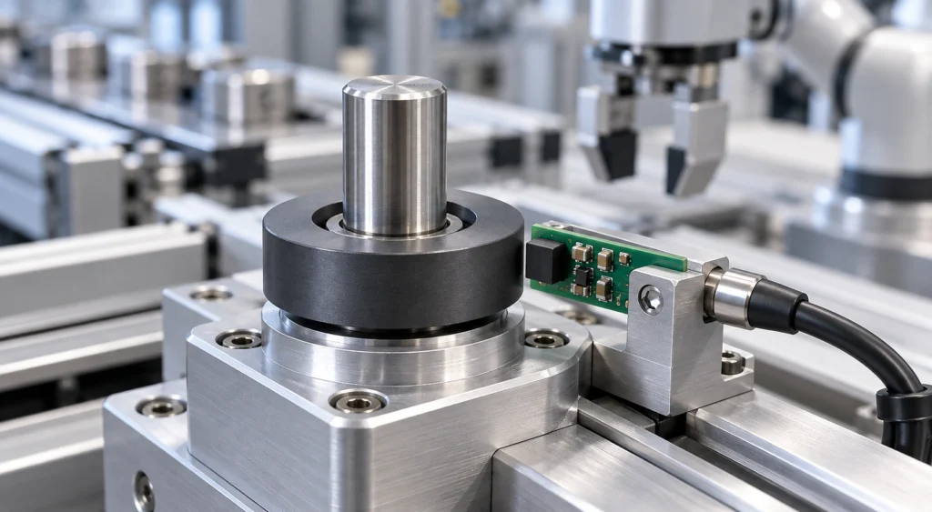
Sensors and industrial automation use permanent magnets as part of a measurement chain rather than as a source of holding force. The magnet supplies a field that the sensor or encoder reads. Depending on the sensing principle, the design may require a bipolar, diametrical or multipole configuration. Required field strength, waveform, pole pitch and air gap are defined from the sensor specification.
Linear Field Distribution
An encoder IC expects the flux to pass from pole to pole in a predictable way, so the magnetic pattern is specified as a signal:
- Pole pitch uniform enough that each transition carries the same electrical angle.
- Field waveform and pole pitch matched to the sensing principle and sensor specification.
- Pole pattern confirmed per project rather than taken from a standard ring.
Tight Dimensional Tolerances
In a sensing position the mechanical air gap is part of the magnetic circuit, so dimensional tolerance, run-out and signal quality are the same problem. Dimensional tolerance and run-out, achieved by molding or finishing as appropriate to the route, are set by the air gap the design requires and confirmed per project, so the gap stays even around the circumference instead of varying as angle or position error.
Temperature Stability & Signal Drift
The magnet works across a wide ambient range, and because the sensor reads the field the magnet produces, the magnet, the air gap and the electronics share one error budget over temperature. The magnet specification is therefore agreed with the ambient range the assembly actually sees, with the range and the grade confirmed per project.
Where the Br windows actually sit
Encoder work is decided by a few material windows, and they sit closer together than the usual "ferrite is cheap, NdFeB is strong" summary implies. Remanence, as published on the material pages:
- Sintered NdFeB — Br 1020–1470 mT, from the N series at 80 °C up to the AH series at 230 °C, per the NdFeB grade table. The strongest window and the highest temperature ceiling.
- Compression-molded NdFeB — Br 300–830 mT, used for rings and geometries where dimensional consistency and a specified pole pattern matter. Lower output than sintered, with tooling, binder and operating temperature settled per project.
- Injection-molded NdFeB — Br 400–630 mT, output depending on powder loading, with PA6, PA12 and PPS as the common binder systems.
- Strontium ferrite — Br 380–460 mT across the hard ferrite table, normally supplied uncoated.
Read the last two lines together and the useful part appears: a strontium ferrite ring's Br band sits inside the injection-molded NdFeB band. For a sensor ring working across a small air gap, moving between them is therefore not a flux cliff but a cost decision — and at a small gap the ferrite ring can supply what the IC needs, which is why that route is evaluated per project rather than dismissed as the cheap option.
Br is not the whole answer, and treating it as the answer is the usual mistake. In a multipole ring the field the IC actually reads is set by pole pitch, radial ring thickness and the gap, so a high-Br material with uneven pitch reads worse than a lower-Br ring that was formed and magnetized properly. That is why pole pitch uniformity is measured on a multi-axis gaussmeter during sampling rather than inferred from a material datasheet.
Recommended Magnet Forms
- Compression-molded isotropic NdFeB and suitable injection-molded NdFeB or ferrite grades can be evaluated. Orientation options depend on the powder, formulation and process; not every bonded grade is isotropic.
- Multipole ferrite rings — evaluated per project where cost matters more than flux; a small air gap and a clean environment are project conditions rather than the only gate for the design, and this form is not offered as a standard series.
- Magnetization pattern is confirmed per project, and pole pitch uniformity is measured during sampling with the method, the equipment and the party agreed for the project, and the record of the measurement is kept.
Key Electromagnetic & Mechanical Requirements
The magnet requirements this application imposes, and what to send us for a first assessment.
Linear Field Distribution
Field quality specified as a signal: waveform, pole pitch and field strength held to the sensor specification.
The field the magnet supplies is read by the sensor, so waveform, pole pitch and field strength are specified from the sensor specification and confirmed per project.
Tight Dimensional Tolerances
Dimensional tolerance and run-out held close enough that the air gap stays even around the circumference.
Air gap is part of the magnetic circuit, so dimensional tolerance and signal tolerance are the same problem.
Temperature Stability & Signal Drift
Signal drift kept within the agreed error budget across the ambient range the assembly actually sees.
The sensor reads the field the magnet produces, so magnet, air gap and electronics share one error budget over temperature; range and grade are confirmed per project.
Common Engineering Challenges
In sensing duty the magnet is a signal element rather than a force element, so the difficulty shifts from pull force to field quality. Pole pitch has to be uniform enough for the sensor IC to read a clean transition, grinding tolerance is part of the magnetic air gap rather than a mechanical detail, and material behaviour over a wide ambient range turns directly into signal drift. Because the error budget is shared between magnet, air gap and electronics, the magnet specification has to be agreed with the sensor datasheet in hand.
Engineering Selection Notes
Selection starts from the sensor datasheet: the flux the IC needs, the air gap it works across and the pole pitch it has to resolve together decide whether a multipole ferrite ring is sufficient or whether a bonded or injection molded NdFeB ring is required. Material choice then follows the environment and the ambient range, because the coefficient of the magnet contributes to the electrical error the designer is budgeting. Dimensional tolerance is specified against the air gap rather than as a machining convenience, and pole pitch uniformity is measured during sampling with the method, the equipment and the party agreed for the project, rather than left to the tooling alone.
Preferred Magnet Grades & Geometries
Multipole bonded and injection molded NdFeB rings, and multipole ferrite rings where cost matters more than flux. The bonded grade is chosen with the powder and the formulation in view rather than assumed isotropic, and pole spacing is measured during sampling with the method agreed for the project.
Request Quote for This ApplicationWhat the Pole Pattern Has to Match
How the magnet is magnetized follows how it works in the machine: the face that faces the air gap, the pole count around that face and the direction the field has to run are read from the assembly, not chosen from a list. If any of that is still open, say so — a sample or a photograph of the existing part is enough to start.
Magnetization feasibility depends on the material, manufacturing process, geometry and required pole pattern. Send us your drawing, sample or magnetization diagram for evaluation.
Magnetization directions and pole patterns explained → · Send the drawing or a sample →