Electric Motors & Drives
Stator arcs and rotor magnets for motors and drives. Wet-pressed ferrite is usual for stators, and cold start sets the demagnetization margin.
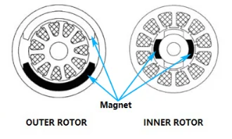
Motors differ in structure, in duty cycle and in where the magnet sits in the magnetic circuit, so the magnet requirement has to be read from your structure rather than from the word motor on its own. The two arrangements below cover most of what we quote. Tell us which one is closer and what the machine has to do, and we will come back with a preliminary material and process judgement and, where it is warranted, a first-round substitution feasibility assessment.
Fixed stator arc segments
Arc segments held in the stator housing or in a cage, facing the rotor across the air gap. Fixed ferrite arc segments are commonly evaluated for permanent-magnet stator assemblies, including brushed DC motors. Pole count and segment layout follow the motor design.
- The air gap is set by the segments seating evenly around the bore, so arc chord, bore radius, arc angle, thickness and segment-to-segment consistency carry it.
- Assembly is piece by piece — bonding, clipping or potting — so bond line, seating repeatability and handling of a brittle ceramic part are part of the magnet requirement.
- What it implies: the magnet job here is an even air gap and even flux around the bore. Grinding an arc for a stator bore is not rotor dynamic balancing, and a concentricity figure on the segment is not a rotor balance specification.
- Submit: bore radius and arc chord or arc angle; segment count per pole and pole pitch; the air gap at working temperature; retention method and the adhesive or clip if known; whether the stator is solid or laminated and segmented; and the temperature the stator reaches in service.
Rotor magnets
Surface-mounted arcs, magnets in pockets or slots, or a one-piece rotor ring in sintered or bonded material, with bonded routes identified as compression molded or injection molded where applicable.
- Retention comes first: sleeve, bonding, over-moulding or pocket wall, against the speed and the centrifugal load it produces.
- The magnet becomes part of the rotating mass, so mass consistency and the balance of the finished rotor — method and grade — are a rotor-level operation agreed with the machine builder. A balance specification belongs to the assembly.
- What it implies: the air gap is set by rotor OD, pocket geometry and run-out as much as by the magnet's own size, and the magnetization pattern has to suit the rotor rather than a generic motor.
- Submit: rotor OD and pocket or segment geometry; retention method; maximum speed and rotor inertia; the balance grade and method applied after magnet assembly; the air gap; orientation and magnetization pattern; and whether a single ring could replace separate segments in your envelope.
What a delivered stator arc actually looked like
Numbers settle a requirement faster than a description does. The arc segments supplied for a water purifier pump motor yoke — two per steel yoke, repeat orders since 2017 — were produced to this drawing: outer radius R35.5 ±0.1 mm, inner radius R27 +0.2/0 mm, wall 8.5 −0.1/0 mm, section 63 ±0.1 × 40 ±0.5 mm, corner breaks 4-R2 on the face and 2-R2 at the ends, 2 × 45° end chamfer, grade Br 380–400 mT / Hcb 230–275 kA/m / (BH)max 27–32.5 kJ/m³, radial magnetization, supplied uncoated and unmagnetized, 30–35 days per batch.
Two things on that drawing are worth carrying into your own. The bore and the wall are toleranced one-sided, and both point the same way: the bore may open by up to 0.2 mm, the wall may come in by up to 0.1 mm, and neither may go the other way. That bias is not arbitrary — it says which side of the part the clearance lives on, so the segment never reaches into the rotor space. And acceptance was settled by fitting two segments into the customer's yoke, not by inspecting a magnet on its own, because the pair has to close the circumference without a step. The full case sets out the rest, including why the parts ship unmagnetized.
Where the grade window sits
Two material families cover this application, and the gap between them is wide enough to decide the design before any grade does:
- Strontium ferrite — Br 380–460 mT, HcB 160–354 kA/m and (BH)max 27.0–41.8 kJ/m³ across the grades listed on hard ferrite. Supplied uncoated. The cold end carries the design risk, because coercivity falls as the temperature falls.
- Sintered NdFeB — Br 1020–1470 mT, with the usable window set by the grade series from N up to AH and up to 230 °C at the top of it, per the NdFeB grade table. Surface protection required. The hot end carries the design risk here, because the reverse field from a hot winding drives a low-coercivity grade towards its knee.
That contrast is the whole reason a grade cannot be picked from the motor label: the same material holds comfortably in one circuit and fails in another, at a temperature set by the winding, the air gap and the duty cycle rather than by the machine type. It is also why the demagnetisation assessment below is written as a per-condition check rather than as a temperature limit.
What to send for an assessment
Send what already exists rather than a completed questionnaire:
- Structure (stator arcs or rotor magnets) and the machine the magnet drives.
- The magnet drawing, or the dimensions you have: arc chord, radius, thickness, tolerance, surface condition.
- Material route if it is already fixed, and the grade if one has been chosen.
- The magnetic circuit: pole count, air gap, back iron path, and whether the winding can impose a demagnetising field on the magnet.
- Operating temperature range at the magnet, from the coldest start to the hottest winding condition, and where those numbers come from — measured, calculated or assumed.
- Duty cycle and load profile: continuous, intermittent or short-duty, taken from your application rather than assumed.
- The worst case the part must survive, if the machine must come through it — a stall, a short circuit, an over-current trip, a blocked rotor.
- Environment and handling: moisture, salt, chemicals, cleaning, and any stress the part sees during assembly.
- Annual quantity, target timing and any delivery constraint. Commercial terms — price, minimum quantity and lead time — are quoted per project.
- The validation the magnet or the machine has to pass: thermal cycling, vibration, salt spray, a life test or a customer-specific sequence, and whether it is witnessed.
If the program carries automotive-grade process expectations — inspection records at a defined level, change control, traceability, submission documents — raise it at the start. Those are project requirements that we confirm with the partner factory that produces and inspects the parts, and with the testing resources coordinated for that project; they are not certifications held by our own operation. Base outgoing inspection is carried out at the factory, and the inspection level is confirmed with the partner factory for the project, and we add a risk-based review per project rather than promising the same routine for every order.
On samples and first orders: for a new customer we work on sample confirmation first, in principle, and a new specification normally needs a sample before a production run; an unchanged, already approved specification runs on that approved standard. Sample quantity, tooling and terms travel with the project quotation.
We do not design your motor and we do not guarantee complete-machine performance. What we own is the magnet requirement, the technical coordination around it — including coordinating the partner factory's engineers with your own where the assessment needs both sides — matching to the right material and process, sampling, production follow-up, export and after-sales, with production carried out in partner factories.
Key Electromagnetic & Mechanical Requirements
The magnet requirements this application imposes, and what to send us for a first assessment.
Flux and air gap at the working geometry
The magnet must hold its flux and its shape at the geometry it runs at in service, not only as a room-temperature block: flux at the magnet's operating temperature, arc chord and pole boundary where they apply, and consistency from segment to segment or ring to ring.
Checked on the drawing and across the set rather than on one part, because segment-to-segment variation shows up as an uneven air gap or as torque ripple. Cogging is an outcome of geometry and drive, so this is one input among several and no single magnet parameter removes it.
Demagnetisation margin across the whole operating range
The grade must hold its flux against the reverse field at the temperatures the magnet actually reaches in service, hot and cold. A hot winding under load is the usual worst case, but strontium ferrite loses coercivity as temperature falls, so for a ferrite design a cold-soak or cold-start condition can be the worst case instead.
Assessed per grade and per operating condition — magnet temperature, the reverse field the circuit imposes, air gap and pole geometry, duty cycle — so there is no one temperature and no one coercivity value that settles it, and the same grade can be adequate in one circuit and not in another. Where the risk cannot be closed from data, an application validation on the assembled magnetic circuit, or a coupon test that reproduces the reverse field, is part of the requirement.
Mechanical integrity and fit in the assembly
The magnet must arrive with the shape, tolerance and surface condition its mounting needs, and survive the assembly route: brittle ferrite arcs are bonded, clipped or potted piece by piece, and a rotor magnet is additionally retained against centrifugal load.
What this means depends on the structure. On a fixed stator the job is even, repeatable seating and an air gap that stays uniform around the bore; on a rotor the magnet becomes part of the rotating mass, so retention, mass consistency and the final balance are a rotor-level operation, and the balancing method and grade are the machine builder's call.
Common Engineering Challenges
Demagnetisation is the risk that most often decides the material and the grade, and it has two ends. A winding that runs hot under load pushes the magnet towards the knee of its curve. Strontium ferrite is the other way round at the cold end, because its coercivity falls as temperature falls, so a cold-soak or cold-start condition can be the worst case for a ferrite design, and it is assessed per grade and per operating condition — the temperature the magnet reaches, the reverse field the circuit imposes, the air gap and the pole geometry, and the duty cycle — never from one temperature or one figure.
Where the assessment cannot be closed from data, the implication is a test rather than a promise: an application validation on the assembled magnetic circuit, or a coupon test that reproduces the reverse field, agreed with you and run with the partner factory's testing resources.
Flux and geometry drift is the second risk. Segment-to-segment variation, chord width and concentricity show up as torque ripple or as an uneven air gap, and a magnet that matches its sample dimensions can still miss once the stack, the bond line and the winding heat are in the picture. The implication is that these values belong on the drawing and are checked across the set, not on one part, and that cogging is a geometry-and-drive outcome rather than something one magnet parameter removes on its own.
Assembly is the third. Hard ferrite is a brittle ceramic oxide, so chipping, edge damage and clamping stress during bonding, clipping or potting are common, and on a rotor the added mass changes the balancing job. The implication is that retention and handling are specified together with the magnet instead of being left to the assembly line.
Late-stage process evidence is the fourth. Where a program expects automotive-grade discipline — inspection records at a defined level, change control, traceability, submission documents — those come from the partner factory's system and from the project's own plan, so they are confirmed with the factory at the assessment stage rather than assumed.
Engineering Selection Notes
Read the structure first, because it decides which requirement binds.
Fixed stator arc segments: the working point is set by the bore radius, the arc chord, the pole-arc ratio, the air gap the segment has to hold and the temperature the magnet reaches beside the winding. The usual route is wet-pressed ferrite arc segments, and the grade follows the demagnetisation assessment at the magnet's operating temperature and reverse field, with the cold end checked as well. Where the envelope is small and the flux has to be high, a sintered NdFeB arc is evaluated instead.
Rotor magnets: the working point is set by the rotor envelope, the speed, retention and the balance the rotor has to end up with. In a small envelope, sintered NdFeB arcs or rings are the route; where volume allows, ferrite arcs, rings, or a bonded or injection-moulded ring can be evaluated, and a single ring is worth testing against separate segments on a rotor.
The operating conditions then decide the grade, not the motor label: temperature at the magnet at both ends of the range, the reverse field the circuit imposes, the magnetic circuit geometry (air gap, back iron, pole number and shape), duty cycle taken from your application, and the application validation the project has to pass — a thermal cycling or life test on the assembled circuit, a coupon test that reproduces the reverse field, or the sequence your own program requires.
Matching follows the same order: material first, then shape and process, then comparable product experience; quality history, existing cooperation, lead time and price come after that.
If nothing in the current range closes the gap at an acceptable risk, we say so at the assessment stage rather than propose a grade that only works on paper.
Preferred Magnet Grades & Geometries
Ferrite arc segments, rings and shaped parts in strontium-based grades: wet pressing for the arcs that need the most flux, dry pressing for simple rings, blocks and shorter arcs, injection moulding where the form is thin-walled or complex. These are the usual starting point for fixed stator arc segment designs.
Sintered and bonded NdFeB arcs, rings and blocks, plus injection-moulded projects: used where the envelope is small and the flux has to be high. Sintered material needs surface protection.
Multipole ferrite rings are an active development focus for us: we will evaluate them against a rotor design, but we do not present a delivery record for them.
Magnetization pattern — axial, diametrical, multipole or radial-oriented multipole — is fixed per project from the structure and the circuit, never assumed from the motor type. The part's geometry follows the drawing: arc chord, radius, thickness and the surface condition the mounting needs.
Request Quote for This ApplicationDocumented project records solving challenges in this application.
- Ferrite Arc Magnets for Water Pump Yokes Delivered Project
An arc segment for a water pur…
- Ferrite Arc Magnets for Fan & Blower Motors Delivered Project
Ferrite arc magnets to drawing…
Technical guides and selection articles for this domain.
- Ferrite vs. NdFeB: Motor Selection Guide Technical Guide
When to pick hard ferrite over…
- How to Specify Magnetization on a Drawing Technical Guide
How to describe magnetization …
What the Pole Pattern Has to Match
How the magnet is magnetized follows how it works in the machine: the face that faces the air gap, the pole count around that face and the direction the field has to run are read from the assembly, not chosen from a list. If any of that is still open, say so — a sample or a photograph of the existing part is enough to start.
Magnetization feasibility depends on the material, manufacturing process, geometry and required pole pattern. Send us your drawing, sample or magnetization diagram for evaluation.
Magnetization directions and pole patterns explained → · Send the drawing or a sample →