Through-thickness Magnetization
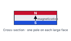
Magnetization runs across the thickness of the part, with one pole on each large face.
Custom strontium ferrite magnets in wet-pressed, dry-pressed and injection-molded forms, tooled to your drawing or sample.
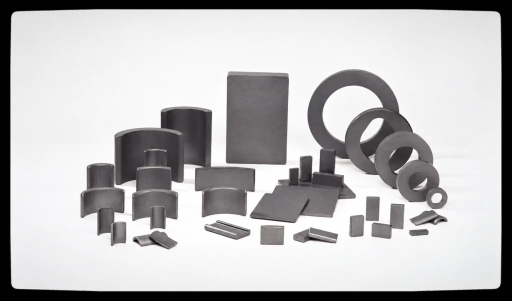
Our ferrite range uses strontium hard ferrite as the magnetic material. Wet-pressed and dry-pressed parts are sintered ceramic magnets. Injection-molded ferrite is a bonded composite of ferrite magnetic powder and a thermoplastic binder. These routes differ in magnetic properties, geometry, tolerances and tooling. We evaluate the route against your drawing, sample and application requirements, with production carried out by selected manufacturing partners.
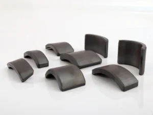
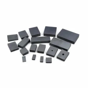
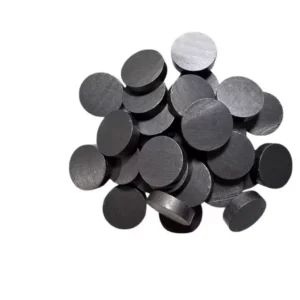
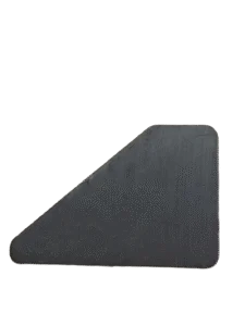
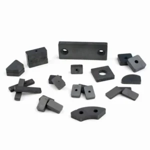
Arcs, blocks, rings, discs, cylinders and trapezoids are the usual shapes, and custom profiles are tooled to the drawing. The trade-off is the same across all of them: ferrite has a moderate energy density, so a design needs enough volume for the flux it asks for. A sintered part is a brittle ceramic oxide that has to be handled and clamped with that in mind; a bonded (injection molded) part is less brittle, but carries a lower flux density. Wet-pressed arc segments are one of the current strengths, and a multipole ring is assessed project by project from the drawing, the material and the tooling.
A project can start from a drawing, from a sample, or from the application and its operating conditions, and the information does not have to be complete to open the conversation. Dimensions, quantity, the magnetic properties or the magnetization pattern, the working temperature and the tolerances are settled through the evaluation and the sample stage, and what is agreed there is what goes into the quotation and the order.
How this material is produced, controlled and supplied: partner-factory manufacturing model, quality and project control, and commercial and shipping.
Standard profiles and custom motor segments are produced on the tooling agreed with the producing partner factory.


This overview shows how ferrite starting materials relate to sintered and bonded permanent magnets. It also identifies ferrite materials used for EMI suppression as a separate application branch. Material composition and processing must be selected for the intended use.
A simplified relationship map, not a complete production sequence. The branches require suitable material compositions and processing conditions; the same calcined material is not automatically suitable for every route or application.
How the map reads: Calcined Ferrite Material leads to Permanent Magnet Applications and then to Powder Preparation, which leads to Sintered Ferrite Magnets and Bonded Ferrite Magnets. In the first branch, Dry Pressing and Wet Pressing both lead to Sintering & Finishing. In the second branch, Ferrite Powder + Binder leads to Plastic / Resin Binder and Rubber / Elastomer Binder, and both of those lead to Forming Method Selected. A separate dashed branch from Calcined Ferrite Material leads to Ferrite Materials for EMI Suppression, which is for reference only and outside the current supply range.
Isotropic magnets have no preferred macroscopic particle orientation; anisotropic magnets have a preferred orientation. Dry pressing can produce isotropic or anisotropic magnets, while wet pressing is commonly used for anisotropic ferrite. Bonded ferrite can also be isotropic or anisotropic, depending on the material and processing conditions. Particle orientation is established during manufacture and is separate from the final magnetization direction and pole pattern.
Ferrite materials used for cable noise suppression are typically soft ferrites. Cable ferrite cores and clamp-on ferrite cores serve a different function from hard ferrite permanent magnets. This branch is included for reference and is outside our current supply range.
Our current ferrite magnet routes are wet-pressed sintered ferrite, dry-pressed sintered ferrite and injection-molded bonded ferrite. The diagram also includes background categories that do not indicate current supply availability.
| Process | Suited to | Limitation |
|---|---|---|
| Wet Pressing | Typically suited to the higher-performance, anisotropic end of the sintered ferrite band — the listed grades span Br 380–460 mT and (BH)max 27.0–41.8 kJ/m³. Forming: a slurry at 30–40 % water content, drained during pressing. | Shape flexibility and production efficiency are constrained by field orientation and slurry drainage requirements. Which of the listed grades is tooled on this route is confirmed against the drawing, because orientation has to be applied during pressing rather than added afterwards. |
| Dry Pressing | Suited to many simple ferrite shapes, drawn from the same listed sintered band — Br 380–460 mT, (BH)max 27.0–41.8 kJ/m³. Forming: dried powder below 10 % moisture, compacted in the press. | Magnetic performance and achievable geometry depend on the grade, orientation and tooling. Dry pressing can produce isotropic or anisotropic parts, so the orientation has to be stated on the drawing rather than assumed. |
| Injection Molding | Suited to complex shapes and integrated magnetic components. Forming: a ferrite and binder compound injected into the mold, with no slurry drainage step. | Lower magnetic output than sintered ferrite: a bonded part sits below the 380–460 mT sintered band, with the value set by powder loading and the binder system rather than by the listed grade table. Temperature limits follow that binder, and the usable range is confirmed per formulation. |
Explore common magnetization directions and pole patterns, including axial, diametric, radial and multipole configurations.
Red = N pole Blue = S pole
Magnetization runs across the thickness of the part, with one pole on each large face.
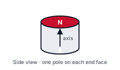
Magnetization runs along the axis, so one end face is N and the other is S.
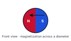
Magnetization runs across a diameter, with the two poles on opposite sides of the part.
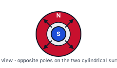
Magnetization runs from the centre outward: one pole on the outer surface, the other at the bore. Which one is N depends on the specification.
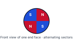
Alternating N and S sectors on one end face, the arrangement used in sensor rotors and small motor rotors.
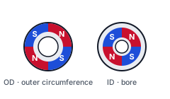
Alternating N and S segments around the outer circumference, around the bore, or around both.
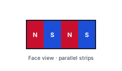
Parallel N and S strips across a face; the strip pitch follows the magnetizing fixture.
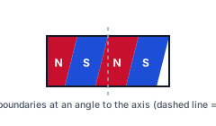
Pole boundaries run at an angle to the axis instead of straight along it; the angle is set by the magnetizing fixture.
Illustrations show magnetization directions and pole patterns. Feasibility depends on the material, grade, geometry and magnetizing tooling, and is confirmed for each project.
Send us your drawing, sample or required pole pattern for evaluation.
Discuss Your Magnetization RequirementsThe ranges in this overview apply only to the sintered grades listed below. These are material reference properties, not surface-field or finished-part flux specifications.
| Material System | Strontium hard ferrite; injection-molded grades combine ferrite magnetic powder with a thermoplastic binder. |
|---|---|
| Production Routes | Sintered: wet pressed, dry pressed. Bonded: injection molded |
| Magnetic Orientation | Anisotropic or isotropic, depending on grade and process |
| Magnetization Pattern | Axial, diametrical, radial or a multipole pattern |
| Listed Grades | Sintered: Y30H-1, Y30H-2, Y32, Y32H-1, Y32H-2, Y33, Y33H, Y34, Y35, Y36, Y38, Y40 |
| Remanence (Br) | Sintered: 380 – 460 mT (3800 – 4600 Gs) |
| Coercive Force (HcB) — Listed Sintered Grades | 160 – 354 kA/m (2010 – 4450 Oe) |
| Intrinsic Coercivity (HcJ) — Listed Sintered Grades | 165 – 360 kA/m (2070 – 4525 Oe) |
| Maximum Energy Product (BH)max — Listed Sintered Grades | 27.0 – 41.8 kJ/m³ (3.4 – 5.3 MGOe) |
| Operating Temperature | Confirmed per grade, process and project |
| Surface Treatment | Sintered ferrite normally requires no coating |
| Grade | Br (mT) | HcB (kA/m) | HcJ (kA/m) | (BH)max (kJ/m³) |
|---|---|---|---|---|
| Y30H-1 | 380–400 | 230–275 | 235–290 | 27.0–32.5 |
| Y30H-2 | 395–415 | 275–300 | 310–335 | 27.0–32.0 |
| Y32 | 400–420 | 160–190 | 165–195 | 30.0–33.5 |
| Y32H-1 | 400–420 | 190–230 | 230–250 | 31.5–35.0 |
| Y32H-2 | 400–440 | 224–240 | 230–250 | 31.0–34.0 |
| Y33 | 410–430 | 220–250 | 225–255 | 31.5–35.0 |
| Y33H | 410–430 | 250–270 | 250–275 | 31.5–35.0 |
| Y34 | 420–440 | 200–230 | 205–235 | 32.5–36.0 |
| Y35 | 430–450 | 215–239 | 217–242 | 33.1–38.2 |
| Y36 | 430–450 | 247–271 | 250–274 | 35.1–38.3 |
| Y38 | 440–460 | 285–305 | 294–310 | 36.6–40.6 |
| Y40 | 440–460 | 330–354 | 340–360 | 37.6–41.8 |
| Property | Symbol | Unit | Value | Notes |
|---|---|---|---|---|
| Recoil Permeability | μrec | — | 1.05–1.3 | |
| Curie Temperature | θc | °C | 460–480 | |
| Temperature Coefficient of Remanence | αBr | %/K | −0.2 | At 0–100 °C |
| Temperature Coefficient of Intrinsic Coercivity | αHcJ | %/K | 0.2–0.5 | At 0–100 °C |
| Density | d | g/cm³ | 4.5–5.1 | |
| Electrical Resistivity | ρ | Ω·cm | ≥10⁴ | |
| Coefficient of Linear Thermal Expansion | αR | K⁻¹ | 7–15 × 10⁻⁶ |
The documents held for this material — grade and property data, and the surface-protection options where they are supplied. Each one downloads as the file was provided.
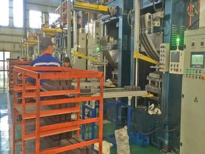
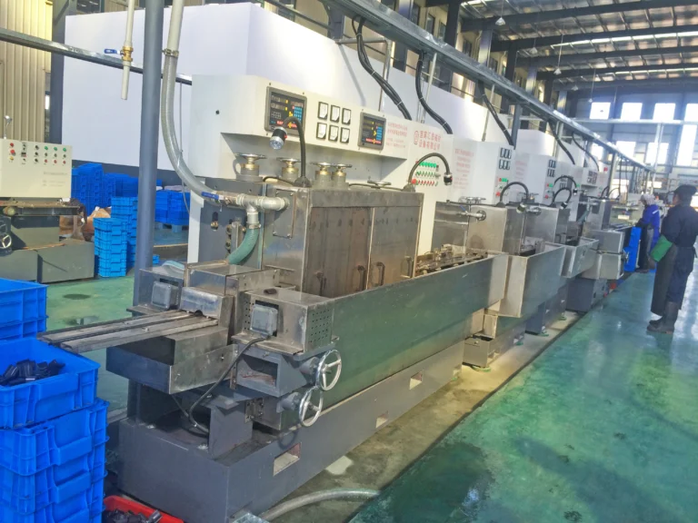
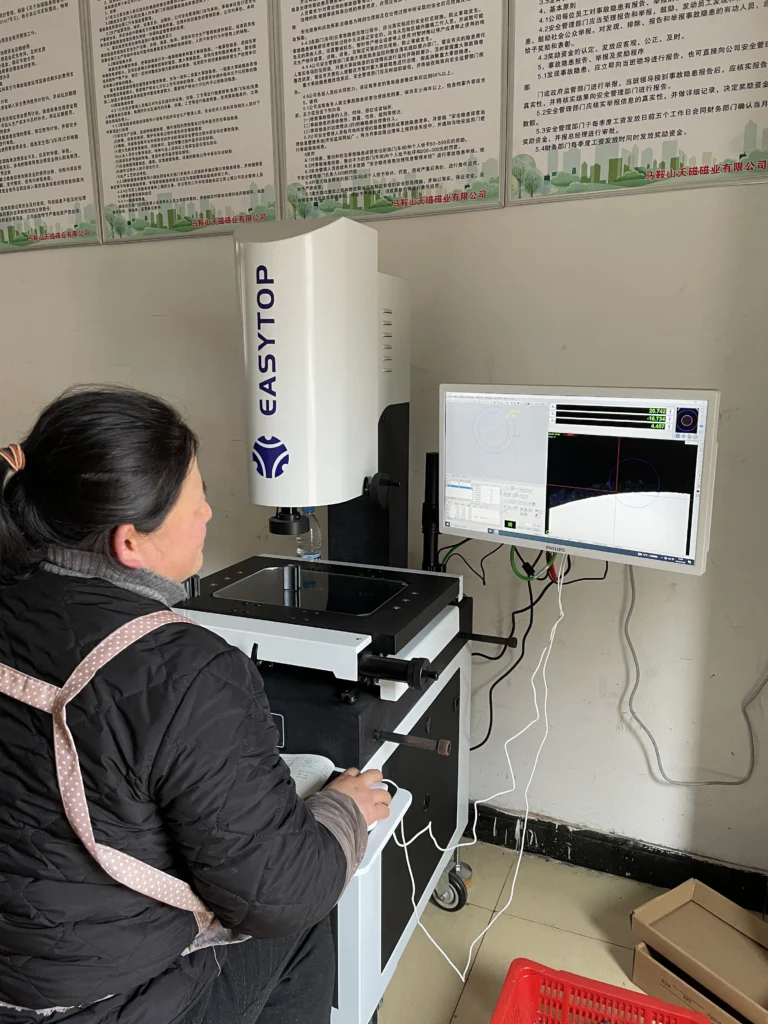
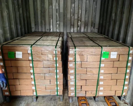
Selected production stages for sintered ferrite magnets, shown at a manufacturing partner’s facility.

Where this material system is used today, with the requirement each application puts on the magnet.
Thermal, environmental and mechanical conditions to review before finalizing the magnet and assembly specification.
Strontium hard ferrite (SrO·6Fe2O3) in three routes: wet-pressed and dry-pressed sintered ferrite, and injection-molded bonded ferrite. The sintered routes carry the higher magnetic properties of the family; the bonded route gives complex shapes, multipole magnetization and a tolerance class agreed per drawing, at a lower flux density. Magnetic orientation, the magnetization pattern and the values that apply are set per grade, per route and per drawing.
Assess the full operating temperature range at the magnet. Ferrite coercivity decreases as temperature falls, so cold-start conditions can be critical for demagnetization. At higher temperatures, magnetic output and the working point must also be checked. Injection-molded ferrite additionally requires review of the binder, moisture exposure and mechanical stability. The usable temperature follows the grade, the route and the demagnetization requirement of the design, so it is fixed per grade and per project rather than by one ferrite figure. Sintered ferrite is a brittle ceramic oxide: it chips at edges and does not tolerate clamping stress, so the assembly has to allow for that, and it normally needs no coating. A bonded part is less brittle and is shaped in the mold, but its temperature limit follows the binder system, and whether it needs a coating is a project decision.Worked example from the coefficients listed in the table below. Strontium ferrite carries a remanence coefficient αBr of −0.2 %/K over 0–100 °C, so the published band moves predictably with the temperature at the magnet. Taking Y30H-1 at 380–400 mT: at 100 °C that is roughly 319–336 mT, because 80 K at 0.2 %/K is about 16 % of remanence; at −20 °C it is roughly 410–432 mT, because 40 K at 0.2 %/K is about 8 %. Two consequences follow for the drawing. The hot end costs flux, so a design that only just closes its torque target at room temperature will not close it in a warm housing, and the check has to be run at the top of the range. The cold end adds flux but takes coercivity away, and that is the more dangerous direction: the flux margin rises while the resistance to demagnetization falls, so a cold start next to a strong opposing field is where a marginal grade fails. Below 0 °C the coefficient above is already an extrapolation, so the demagnetization check at that temperature — not the arithmetic — is what fixes the grade.
Choose ferrite when the design has enough volume for the flux it needs, when cost stability at volume matters, and when the working point of the magnetic circuit is defined well enough to fix a grade. Fix the route first - wet pressed, dry pressed or injection molded - because that decision sets the flux density band, the tolerance class and the tooling cost, and it is made on the drawing or the sample. Ferrite is a poor fit where the magnet has to sit in a very small envelope at high torque, where a very high (BH)max is required, or where parts must take impact without support. A first review needs dimensions, quantity, the magnetic or magnetization requirement, the working temperature and the tolerances; anything not fixed yet can be left open and settled in the evaluation.
Documented project records that reference this material system.
An arc segment for a water pur…
Ferrite arc magnets to drawing…
Technical selection notes and engineering articles.
When to pick hard ferrite over…
What to confirm before a custo…
How critical tolerances are re…
How to describe magnetization …
No drawing, grade or magnetiza…
B-grade and surplus ferrite ar…
Send us your 2D/3D CAD drawings, sample parameters, or operating temperature requirements. We make a first-round feasibility judgement and typically reply within 3 business days; a technical evaluation takes as long as the information and the project require.