Material System
Magnet Geometry
Arc Segment
Arc segments close a stator or rotor circumference from separate pressed pieces, specified by their radii, arc angle, wall thickness and length.
Why an arc segment instead of a complete ring
A stator or a rotor of any real diameter cannot always take a one-piece ring, so the magnet is pressed as a segment and the segments are assembled. An arc segment is specified by inner and outer radius, arc angle or chord width, wall thickness and length, and by whether the part is fixed in a stator or retained on a rotor. Each of those is a drawing question, not a catalogue one.
What the drawing has to fix
- Geometry — inner and outer radius, arc angle or chord width, wall thickness, length.
- Mounting — fixed in a stator, or retained on a rotor.
- Assembly — a segment separated from its neighbours needs its positioning and retention checked in the assembly, not only on the single piece.
- Orientation — for anisotropic ferrite, the magnetic direction has to be compatible with the orientation established while the part is pressed.
- Magnetization — the radial pole count, and the datum the poles are dimensioned from.
The last two are the ones most often left off a drawing. Orientation and magnetization are separate steps: orientation is established while the part is formed, magnetization is applied afterwards.
Ferrite arc segments are wet pressed
On the wet-pressed route the ferrite is compacted as a slurry at 30–40 % water content and that water is drained during pressing. It is the water that lets the particles align as the part is formed, which is why the route is used where the arc geometry and the flux requirement both matter. Dry pressing dries the same slurry below 10 % moisture before compaction: it is the economical route for simple geometries and cost-sensitive repeat production, and a part that needs more flux per unit volume than that alignment gives is reviewed against wet pressed ferrite. Arc segments sit on the wet side of that line.
Magnetization is radial — the pole count is what varies
Tile segments are magnetized radially: the flux crosses the wall thickness of the arc, so the pole face is the inner or the outer surface. Radial two-pole, four-pole and six-pole magnetization are all produced on this geometry. Which one applies follows from the circuit; the pole count, the pitch and the angular position of the poles are set by the magnetizing fixture and confirmed on the drawing. The pressed orientation has to serve that same radial direction, which is why an anisotropic ferrite arc is pressed and magnetized as one commitment rather than two separate ones.
Tolerances follow the part, not the shape
There is no single tolerance band for “arc segment”. What a segment can hold depends on the actual dimensions of the part: the inner and outer radius, the wall thickness, the arc angle, the length. A thin-walled segment on a large radius and a thick segment on a small one do not hold the same band, so the tolerance is agreed against the drawing’s dimensions rather than quoted as a figure for the shape. That is also why the drawing has to carry real dimensions — without them there is nothing to hold to.
Surface and grade
Tile ferrite segments are normally supplied uncoated. Where an assembly calls for a coating, it is stated on the drawing and confirmed per project.
The grade is not fixed by the geometry either. It follows the performance the circuit needs: the hard ferrite grade table is the range to choose from, and a high-performance grade is selected against the customer’s requirement rather than assumed because the segment is small or the air gap is tight.
Magnetized or unmagnetized delivery
Neither state is the default in itself. Segments can be delivered magnetized or unmagnetized, and which way a project goes follows the customer’s assembly — whether the magnet is bonded, clamped or potted into a stack before the field is applied, or whether it goes straight into the circuit in the state it arrives. The choice is usually settled by handling on the customer’s line rather than by the magnet: an unmagnetized segment can be assembled and then magnetized with the assembly in place, while a magnetized one has to be handled as a magnet from the moment it is picked up.
What does not change either way is the drawing. The magnetization direction, the radial pole count and the datum the poles are dimensioned from are fixed before shipment regardless of whether the field is applied, because the magnetizing fixture is built to that drawing. A drawing that marks the delivery state — magnetized, or supplied unmagnetized — removes the one question that is otherwise asked at dispatch. The sketch on this page states it in the title block, which is the clearest place for it.
Material systems and routes
This geometry is worked here in the routes listed further down this page: wet-pressed ferrite, and the sintered and compression-molded NdFeB routes. Each route page states what that route is confirmed for. A route that is not listed for a shape says the route is not confirmed for it — not that the geometry cannot be made.
What to send for an arc-segment review
- The drawing, or a sample: inner and outer radius, arc angle or chord width, wall thickness, length.
- Whether the part is fixed in a stator or retained on a rotor, and how it is held.
- N and S on the sketch, the radial pole count — two, four or six — and the datum the poles are dimensioned from.
- The grade requirement, or the flux the circuit needs, if it is already fixed.
- Whether the assembly needs a coating.
- Whether the segments are to arrive magnetized or unmagnetized.
Send it through the technical review form; datasheets and route diagrams are in the download library, and documented arc-segment projects are collected under case studies.
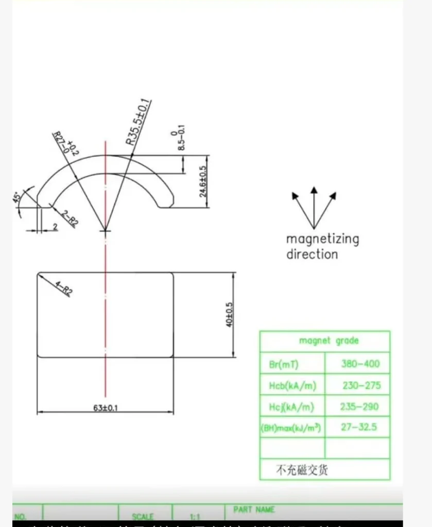
Specification
What the Drawing Has to State
The dimensions a drawing has to settle before this part can be quoted, and what each one decides.
| Parameter | What the drawing states | What it decides |
|---|---|---|
| Outer radius (Ro) | Radius to the outer arc face, dimensioned from the datum the drawing names. | Sets the air gap at the bore and the concentricity of the segment once it is in the assembly. |
| Inner radius (Ri) | Radius to the inner arc face. | Sets the wall thickness, and the clearance to the rotor or shaft the segment closes around. |
| Wall thickness | The radial dimension between the two arc faces. | Carries the flux across the wall, so it follows what the circuit needs rather than a stock size. |
| Arc angle or chord width | One of the two, with the number of segments that fill the circle. | Decides how many segments close the circumference and where the joints between them fall. |
| Length (axial) | Length along the axis of the assembly. | Sets the pole area, and it has to match the stack height the assembly allows. |
| Magnetization | N and S on the sketch, the radial pole count (two, four or six) and the datum the poles are dimensioned from. | Built into the magnetizing fixture, so it is settled before tooling rather than at dispatch. |
| Delivery state | Magnetized, or supplied unmagnetized. | Decides how the part is handled on the line, and whether the field is applied with the assembly in place. |
Tolerance is agreed against the dimensions on the drawing, not quoted as a band for the geometry: a thin-walled segment on a large radius and a thick segment on a small radius do not hold the same one.
Material Systems
Materials Offering This Shape
Material systems tooled in this geometry, each with its own grade range and manufacturing route.
Material System
Neodymium (NdFeB) Rare Earth Magnets
Manufacturing Routes
How This Shape Is Made
The production routes this geometry is confirmed in. Only the routes confirmed for the shape are listed here, and a shape with none listed is not a statement that it cannot be made.
Applications
Explore Applications for the Related Materials
Explore application guidance for the materials listed above. Suitability of this geometry is evaluated against the specific assembly and operating requirements.
Project Evidence
Case Studies
Documented project records that reference the materials offering this shape.
Technical Notes
Articles on This Shape
Technical notes that treat this geometry as their subject: how it is specified, magnetized and held to tolerance. Notes that only mention the shape in passing are not listed here.
Technical Note
B-Grade & Surplus Ferrite Arc Magnets
Custom Tooling
Need a Custom Arc Segment Magnet?
Send the 2D/3D drawing or the dimensional specification for this geometry. Tooling feasibility is assessed against the material system you intend to use, and we reply typically within 3 business days; the assessment itself takes as long as the drawing and the project require.