Industrial Equipment & Couplings
Magnetic separators, conveyor fixtures, non-contact magnetic couplings, lifting magnets, and heavy-duty industrial holding assemblies.
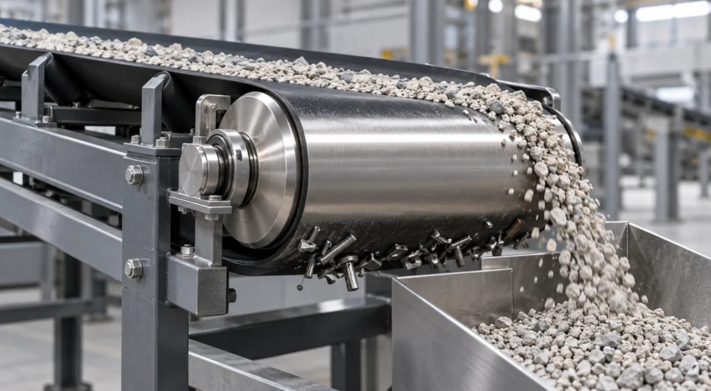
Industrial equipment and couplings are the applications where the magnet is a fixture or a working tool as much as a motor component: magnetic separators, conveyor fixtures, non-contact magnetic couplings, lifting magnets and heavy-duty holding assemblies. Here the specification is written around holding or clamping force, around how the part is mounted, and around repeatability across long production runs that may be spread over several assembly lines. The three requirements below are what shape the magnet specification in this application.
Holding & Clamping Force
A holding magnet, a coupling or a separator is judged by the force it develops at the working gap, not by a material figure on its own. The field has to penetrate deeply enough through the gap and through whatever steel sits in the circuit, and the assembly has to keep that force after the mechanical shock of lifting, indexing and conveyor service.
- Deep field penetration is the performance requirement, so the design is written around the real working gap of the assembly rather than around the bare magnet.
- Structural resistance to mechanical shock is part of the same requirement: a lifting magnet or conveyor fixture is clamped, released and occasionally dropped, and both ferrite and NdFeB are brittle materials.
- Where the required force has to fit a limited footprint, volume for volume NdFeB delivers higher flux than ferrite, and the grades are compared per project, which is why high-grade sintered NdFeB blocks are used in the compact high-force designs.
Define the acceptance criterion for the assembly: holding force at a stated gap and contact condition for holding systems, transmitted torque and slip conditions for couplings, or field and separation performance for separators. These requirements depend on the magnetic circuit and assembly, not on the magnet grade alone.
Mounting Features & Mechanical Support
The magnet has to be mountable in a workshop, not only magnetically strong. Countersunk holes let the part be fastened instead of bonded, threaded steel cups provide a ready-made housing for holding assemblies, and precision-ground flat mating faces can be specified so the magnet seats against the fixture; flatness and the joint condition are stated on the drawing.
- Countersunk or other machined features are evaluated against the material, geometry and remaining wall thickness; feasibility is confirmed per drawing and per route before tooling is proposed.
- Threaded steel cups are a common mounting route for holding magnets, because the cup both houses the magnet and closes the magnetic circuit on the working face. Where a threaded interface is used, the thread is formed in the steel cup or housing rather than in the magnet.
- Precision-ground flat mating faces are specified so the magnet seats against the fixture without a gap, and because ferrite and NdFeB are brittle, the mounting feature and the clamping method are settled before tooling.
Large Batch Uniformity
A separator, a coupling or a lifting magnet is judged by what every unit holds, so repeatable magnetic pull force has to survive being produced across multiple assembly lines. That makes the grade, the forming route and the magnetization pattern a frozen part of the specification rather than a per-batch choice.
- Repeatable pull force is the acceptance criterion, checked across batches and lines rather than on a first-article sample alone.
- Fixing the material route keeps the field consistent: dry-pressed ferrite blocks and discs are produced to the drawing, and their grade and geometry are confirmed per batch, which is why they suit high-volume industrial assemblies.
- Where several lines build the same assembly, the magnetization direction and the mounting features are confirmed once per project and then held.
The numbers here, and what they are not
This is the one application where a table of material figures can mislead, so it is worth being explicit about which numbers do the work. The published remanence windows are the starting point: strontium ferrite Br 380–460 mT and sintered NdFeB Br 1020–1470 mT, as listed on the hard ferrite and NdFeB grade tables. Volume for volume that is roughly two and a half times the flux on the NdFeB side, and that ratio is what allows a compact high-force design to exist at all.
What none of those figures tells you is the force the finished assembly will develop. Holding force belongs to the whole circuit: the working gap, the steel in the magnetic path, the contact condition of the mating faces, and — for a coupling — the axial offset and the slip the design can tolerate. A pull force quoted on a bare magnet is measured against a polished plate at zero gap, which is not the condition a separator, a conveyor fixture or a coupling ever runs in. That is deliberately why this page carries no pull-force table: such a number would be quotable and wrong.
The practical consequence is short. Send the working gap, the steel in the circuit and the force or transmitted torque the assembly has to develop, and the grade comparison is done against those rather than against a datasheet headline; the acceptance criterion is then written at that gap, on the assembly. What we do commit to is repeatability — which is why the grade, the forming route and the magnetization pattern are frozen once per project and then held across lines.
Recommended Magnet Forms
Ferrite blocks and discs cover the cost-driven, high-volume side of this application, and high-grade sintered NdFeB blocks cover the compact high-force side:
- Ferrite blocks and discs — dry pressing is the economical route for simple blocks, discs and rings.
- High-grade sintered NdFeB blocks — sintered NdFeB is used where flux has to be maximized inside a small footprint, so a holding magnet or coupling that must fit a limited footprint can still develop the required force.
- Mounting features such as countersunk holes and ground mating faces are specified on the production drawing, and magnetization direction is confirmed per project: axial, diametrical, multipole and radial-oriented multipole magnetization can be produced, and the pattern that applies is settled per project against the tooling.
Key Electromagnetic & Mechanical Requirements
The magnet requirements this application imposes, and what to send us for a first assessment.
Holding & Clamping Force
Deep magnetic field penetration and structural resistance to mechanical shock.
Force is specified at the working gap of the finished assembly and against the shock the fixture sees in service, not as a bare material figure.
Mounting Features & Mechanical Support
Countersunk holes, threaded steel cups, or precision-ground flat mating faces.
The mounting feature belongs on the production drawing, and because both ferrite and NdFeB are brittle it is settled before tooling. Countersunk holes are evaluated per material, geometry and remaining wall thickness, and threaded cups provide the thread rather than the magnet.
Large Batch Uniformity
Repeatable magnetic pull force across multiple assembly lines.
Repeatability is a manufacturing discipline: grade, forming route and magnetization pattern are fixed once per project and then held across lines.
Common Engineering Challenges
The recurring difficulty in industrial holding and coupling work is that magnetic performance and mounting are designed separately: pull force is quoted at the magnet, while the assembly works at a gap and through a steel cup, so the two have to be reconciled before tooling. Mechanical shock is the second pressure point, because ferrite and NdFeB are both brittle and a lifting or conveyor fixture is clamped, indexed and occasionally dropped in service. Multi-line production adds a third constraint, since repeatable pull force across batches and lines depends on freezing the grade, the forming route and the magnetization pattern. The cost decision then usually falls between a ferrite block or disc, which is normally supplied uncoated, and a high-grade sintered NdFeB block that delivers the same force in far less volume.
Engineering Selection Notes
Selection starts from the force the assembly has to develop at its real working gap and from the mechanical loads the part will see, because a separator, coupling, lifting magnet or conveyor fixture is judged by what it holds or transmits. Mounting is the second decision: countersunk holes, threaded steel cups and precision-ground flat mating faces have to be on the drawing before tooling, and both ferrite and NdFeB are brittle, so the clamping method matters as much as the magnet grade. The material route then follows the volume available, with ferrite blocks and discs where the footprint is generous and bill-of-materials cost and whether an uncoated part suits the exposure decide, or high-grade sintered NdFeB blocks where the same force must fit a small envelope at higher cost and with surface protection selected against the exposure. For multi-line production the grade, forming route and magnetization pattern are frozen so pull force stays repeatable batch to batch. Magnetization is confirmed per project.
Preferred Magnet Grades & Geometries
The typical forms are ferrite blocks and discs, or high-grade sintered NdFeB blocks. Dry-pressed ferrite is the economical route for simple blocks, discs and rings. Hard ferrite is a ceramic oxide that is normally supplied uncoated, and whether a coating is needed is confirmed against the exposure. Where the fixture can accept the volume, ferrite is the cost-stable choice for separators, conveyor fixtures and large holding assemblies.
High-grade sintered NdFeB blocks are used where flux has to be maximized inside a small footprint, at higher material cost and with mandatory surface protection. Blocks are supplied plain, or with machined mounting features such as countersunk holes, where the material, geometry and remaining wall thickness allow it. The magnetization direction is confirmed per project.
Request Quote for This ApplicationWhat the Pole Pattern Has to Match
How the magnet is magnetized follows how it works in the machine: the face that faces the air gap, the pole count around that face and the direction the field has to run are read from the assembly, not chosen from a list. If any of that is still open, say so — a sample or a photograph of the existing part is enough to start.
Magnetization feasibility depends on the material, manufacturing process, geometry and required pole pattern. Send us your drawing, sample or magnetization diagram for evaluation.
Magnetization directions and pole patterns explained → · Send the drawing or a sample →