Material System
Magnet Geometry
Rectangular Block
Rectangular block magnets: specify length, width and thickness, plus the working face, the pole faces and the dimensions that set the assembly gap.
A rectangular block is three numbers and two faces
Length, width, thickness, and then the parts of the drawing that are usually missing: which two faces carry the poles, which face seats against the assembly, and how tight the dimensions that matter have to be. A rectangular block is the easiest geometry to draw and the easiest to under-specify — a sketch can be perfectly clear about the length and width and still leave the thickness, the working face and the polarity open, which are the three things that decide whether the part works in the gap. The fourth is tolerance, and on this geometry it decides more than a number: it decides how the part is made at all.
Block, rectangle or tile
Three words are used for this geometry, and the choice tends to follow the proportions rather than the material. A plate whose footprint is large against its thickness is usually called a rectangle; a small part whose length, width and thickness are close — a cube, or near it — is usually called a block. On a drawing they are the same family, and the questions to answer are identical: three dimensions, the working face, the pole faces, the tolerance. The word on the enquiry does not change the part, so this page covers both.
Which two faces carry the poles
Through-thickness is the common arrangement: one pole on each large face, so the flux crosses the thinnest dimension of the part. That is also the arrangement a moulded block reaches most directly, because the part is compacted along one straight line — normally its thickness — and an anisotropic grade is oriented in that same direction as it is pressed.
Two alternatives are specified on this geometry: poles on opposite narrow faces, so the flux crosses the length or the width instead of the thickness, and a striped pattern across one face, where parallel N and S strips sit on the working face and the strip pitch follows the magnetizing fixture. The striped arrangement is the one used where a block acts as an encoder or a sensor track rather than as a field source. The pole patterns and what sets each one are laid out separately.
Whichever applies, the drawing has to say it: which faces, where the boundary between poles falls, and which corner the pattern is dimensioned from.
Moulded, or cut from a larger block
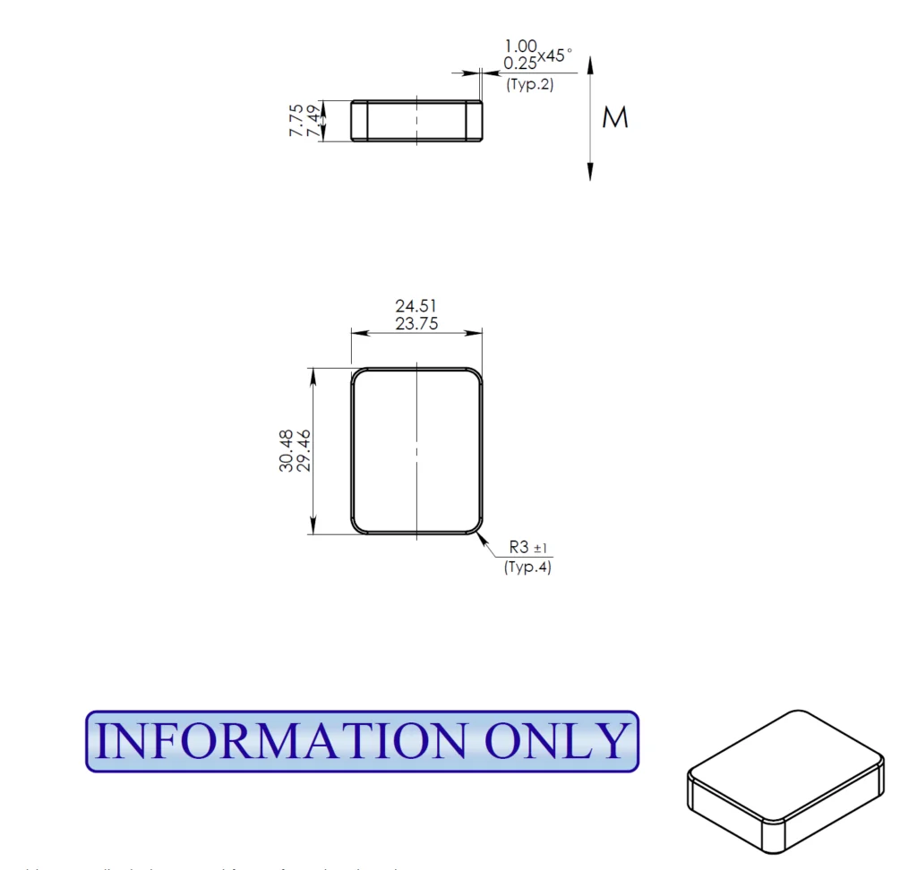
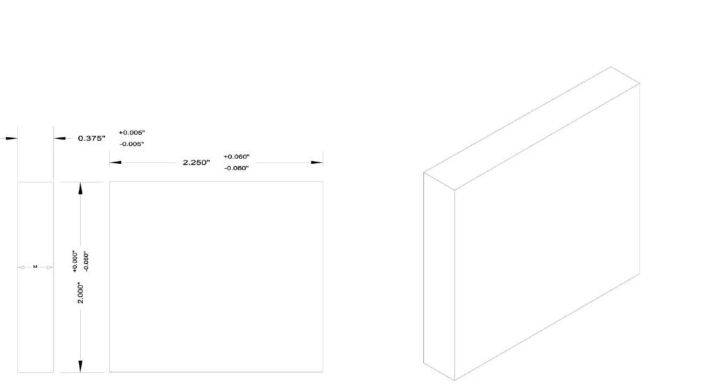
A rectangular block does not have to be formed as one. There are two ways to reach the size, and the drawing decides which applies. Moulding compacts the powder in a die cut to the finished outline, which is the first of the two sketches at the end of this page. Cutting takes a large pressed block down to the required dimensions and finishes it, which is the second.
The reason cutting exists is tolerance, not shape. Where the requirement is tighter than pressing to net shape reaches, cutting gives the dimensional control the die cannot. That control has a cost, and the cost comes from the material: ferrite is brittle, a brittle material does not want to be cut, and cutting therefore costs more than moulding the same part. It is not a better route — it is a route bought with a tolerance requirement. It is also a route with a shape it applies to: blocks and long strip forms are the geometries that get cut, and the rest are moulded, because there is no reason to pay for cutting a shape a die already holds.
What follows for a drawing is that the tolerance has to be stated dimension by dimension. A block with a generous outline and one critical thickness, a block with four tight dimensions and a block with no tolerance stated at all are three different propositions, and they do not price or schedule the same way. Cutting a part that did not need it, or pressing a part that cannot hold its dimension, are both avoidable — provided the dimensions that matter are marked.
Sharp or rounded: reading the route off the drawing
There is a visual tell, and it is reliable enough to read a part with no paperwork: look at the corners. A moulded block has radii where the faces meet, because the corner is formed by the die cavity and comes out round; the working edge is often chamfered for the same reason. A cut block has sharp, square edges, because the corner is produced by a tool taking material away rather than by a cavity, and nothing rounds it unless the drawing asked for a break edge.
The two sketches at the end of this page are that comparison. The first is moulded: R3 at the outline corners and a 1 × 45° chamfer on the working face, both of them die features and both written on the drawing. The second is cut: square corners, prismatic edges, no radius anywhere.
Read the other way round, the same tell is an instruction. If the part is to come out of a die, mark the radii and any chamfer, because a sharp corner in a die is a corner that chips. If the part is to be cut, the sharp corner is already telling you so, and a drawing that carries it is a drawing that has chosen its route.
Both ferrite routes are open on this geometry
Where a block is moulded, both ferrite routes are open on it — which is where this shape differs from something like an arc segment. Blocks are confirmed here on dry-pressed ferrite as well as on wet-pressed ferrite, and on the sintered and compression-molded NdFeB routes.
The two ferrite routes work the same strontium ferrite system and differ in the moisture at forming. Dry pressing dries the slurry below 10 % moisture and compacts free-flowing powder in one stroke, with an orienting field applied for an anisotropic grade; it is the economical route for simple geometries and repeat production, and a rectangular block is about as simple a geometry as a die will see. Wet pressing compacts the slurry at 30–40 % water content and drains that water during pressing, and the water is what lets the particles align as the part forms.
The practical consequence is a cost lever rather than a technicality: a block whose flux requirement is higher than a dry-pressed alignment gives can move to wet pressing inside the ferrite system, instead of being pushed up to NdFeB on the assumption that more flux means a more expensive material. Which of the two applies is decided against the flux the circuit needs, not by the shape.
Sintered NdFeB blocks may be ground
Sintered NdFeB is the route where the finishing step does real work: critical faces can be ground after sintering, which is how the tightest dimensions and the cleanest edges on a block are actually reached. It is also a cost step, so the drawing should say which faces need it. A face that only has to clear the assembly does not need grinding; a face that sets the air gap usually does. Achievable features and finishing depend on the material and the route, and are confirmed per part rather than assumed from the shape.
Grade and coating
A block does not imply a grade. The hard ferrite grade table is the range for the ferrite routes; the NdFeB grade range covers the sintered and compression-molded routes. If the flux, the operating temperature or the demagnetizing field of the assembly is already fixed, that is what selects the grade — and it may select the route as well, which is why the two questions are worth sending together.
Pressed ferrite blocks are normally supplied uncoated, and where an assembly calls for a coating it is stated on the drawing and confirmed per project. On NdFeB the coating is part of the specification rather than an afterthought, and the system is agreed against how the part is handled and what it is exposed to.
Tolerances follow the part — and choose the process
There is no tolerance band attached to “block” or to “rectangle”. The requirement is matched to what the assembly actually needs, dimension by dimension: the thickness and the parallelism of the two working faces are usually what the air gap depends on, while the outline dimensions are the easier ones. An as-pressed ferrite block, a block cut to size and a ground NdFeB block do not hold the same band on the same drawing, so the number has to be agreed against the dimensions that matter rather than quoted for the shape.
The second sketch on this page shows the asymmetry that makes a part a candidate for cutting: its outline is dimensioned at ±0.060 in and its thickness at ±0.005 in. One loose dimension and one that is not — and the tight one is what the route is bought for.
So on this geometry the tolerance does more than set a limit: it selects the process. State which dimensions are tight and the choice between moulding and cutting follows from the drawing; leave the tolerance out and the quotation has to assume one or the other.
Material systems and routes
This geometry is worked here in the routes listed further down this page: wet-pressed ferrite, dry-pressed ferrite, and the sintered and compression-molded NdFeB routes. Those are the forming routes; cutting to size sits on top of them and is agreed per project. Each route page states what that route is confirmed for, and a route that is not listed for a shape says the route is not confirmed for it — not that the geometry cannot be made.
What to send for a block review
- Length, width and thickness, with the working face identified on the sketch.
- Which two faces carry the poles, with N and S marked — or, for a striped pattern, the strip direction and pitch.
- The tolerance requirement, dimension by dimension: this is what decides moulded or cut.
- Whether the corners and edges are to be rounded and chamfered (moulded) or left sharp (cut), if either matters to the assembly.
- How the block is retained in the assembly, and the gap or clearance it has to hold.
- The grade requirement, or the flux, temperature and demagnetizing field the circuit needs.
- Which faces, if any, need grinding or a coating.
- Whether the parts are to arrive magnetized or unmagnetized, since that decides how they are handled before assembly.
Send it through the technical review form; grade tables and route diagrams are in the download library, and documented projects are collected under case studies.
Specification
What the Drawing Has to State
The dimensions a drawing has to settle before this part can be quoted, and what each one decides.
| Parameter | What the drawing states | What it decides |
|---|---|---|
| Length and width | The two in-plane dimensions of the working face. The sketches on this page state 30.48 × 24.51 mm for a moulded block and 2.250 × 2.000 in for a cut one. | Sets the pole area of the face that works in the gap. |
| Thickness | The dimension across the pole direction — 7.75 mm on the moulded sketch here, 0.375 in on the cut one. | Sets the flux path, and on most blocks it is the dimension the part is pressed along. |
| Pole faces | Which two faces carry the poles, marked N and S, and which corner the pattern is dimensioned from. | Decides the magnetization direction, and how the block sits in the circuit. |
| Corners and edges | Radii or a chamfer on a moulded block — R3 and 1 × 45° on the sketch here — and square edges on a cut one. | Reads off the route: a sharp corner in a die is a corner that chips. |
| Tolerance | Stated dimension by dimension rather than in a general block; the cut sketch here carries ±0.060 in on the outline and ±0.005 in on thickness. | Decides whether the part is moulded or cut, and the two do not price or schedule the same way. |
| Magnetization pattern | Through thickness, across the narrow faces, or a striped pattern with its pitch. | Assessed per structure, so the pattern follows the circuit and is not one by default. |
| Delivery state | Magnetized, or supplied unmagnetized. | Settles handling, and whether the field is applied with the assembly in place. |
There is no single tolerance band for a block: what the part holds follows its own dimensions and the route it is made on, which is why the two are agreed together.
Material Systems
Materials Offering This Shape
Material systems tooled in this geometry, each with its own grade range and manufacturing route.
Material System
Neodymium (NdFeB) Rare Earth Magnets
Manufacturing Routes
How This Shape Is Made
The production routes this geometry is confirmed in. Only the routes confirmed for the shape are listed here, and a shape with none listed is not a statement that it cannot be made.
Applications
Explore Applications for the Related Materials
Explore application guidance for the materials listed above. Suitability of this geometry is evaluated against the specific assembly and operating requirements.
Project Evidence
Case Studies
Documented project records that reference the materials offering this shape.
Custom Tooling
Need a Custom Rectangular Block Magnet?
Send the 2D/3D drawing or the dimensional specification for this geometry. Tooling feasibility is assessed against the material system you intend to use, and we reply typically within 3 business days; the assessment itself takes as long as the drawing and the project require.