Injection Molded NdFeB
NdFeB powder in a thermoplastic binder. Suits sensor rotors and small actuators; output is below sintered NdFeB and the binder sets the heat limit.
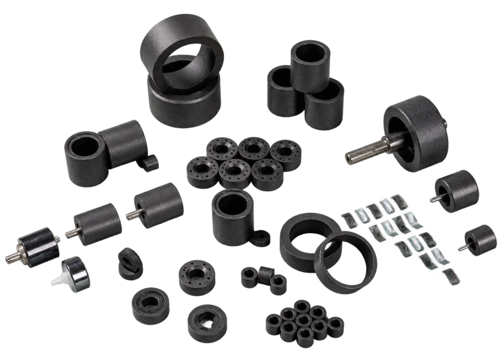
Injection molded NdFeB combines NdFeB magnetic powder with a thermoplastic binder. Common thermoplastic binder systems include PA6 (Nylon 6), PA12 (Nylon 12) and PPS. This page presents isotropic injection-molded NdFeB materials. The compound is injected into a mold to form the part geometry. Parts can be molded as standalone magnets or integrated with suitable inserts through insert molding. Insert compatibility and integration feasibility are evaluated per project.
How the part is formed
- NdFeB powder is compounded into a thermoplastic pellet, so the machine receives a material it can inject rather than a powder that has to be compacted.
- The mold sets the geometry — bore, bosses, wall sections and the face the poles sit on — and the compound fills it in one cycle.
- Where the design allows, a shaft or insert is placed in the tool and the magnet is molded around it; insert compatibility is evaluated per project.
- The part is magnetized after molding in a fixture, and any post-machining is confirmed against the drawing.
Position sensor rotors, micro-actuators and contactless throttle sensors are the duties this route is specified for; the application guidance sits in Sensors & Industrial Automation and Automotive Auxiliary Systems.
Injection Bonded NdFeB Reference Data
The values below are reproduced from the injection bonded reference table for this route. They apply to the listed injection bonded grades only; sintered and compression molded NdFeB are specified separately.
Magnetic Properties
| Grade | Br (mT) | Hcb (kA/m) | Hcj (kA/m) | (BH)max (kJ/m³) |
|---|---|---|---|---|
| NBI-4 | 400–490 | 256–312 | 576–736 | 28–36 |
| NBI-6 | 490–570 | 312–384 | 640–800 | 40–56 |
| NBI-6M | 480–560 | 336–400 | 960–1360 | 44–60 |
| NBI-8 | 570–630 | 382–430 | 680–840 | 60–68 |
Physical Properties
| Grade | Density (g/cm³) | Recoil permeability | Br coefficient | Magnetizing field (kA/m) | Ring crushing strength constant (N/mm²) |
|---|---|---|---|---|---|
| NBI-4 | 4.0–4.5 | 1.1–1.22 | −0.10 | 1592 | > 78 |
| NBI-6 | 4.5–5.5 | 1.1–1.22 | −0.09 | 1592 | > 78 |
| NBI-6M | 5.0–5.5 | 1.1–1.22 | −0.10 | 1990 | > 78 |
| NBI-8 | 5.0–5.5 | 1.1–1.22 | −0.10 | 1592 | > 78 |
The values listed are for reference. Actual properties should be verified by testing the finished product.
Core Process Characteristics
The material this route works in, the advantage that decides it, the limitation to plan around, and the parts it is normally specified for.
| Primary Material | Neodymium (NdFeB) Rare Earth Magnets |
|---|---|
| Core Advantage |
|
| Key Limitation |
|
| Typical Applications |
|
Process Characteristics
The parameters recorded for this route, each with the note that says how it is confirmed on a project.
| Material System | NdFeB magnetic powder compounded with a thermoplastic binder Properties depend on the powder, powder loading and binder system. |
|---|---|
| Binder Type | Common systems: PA6 (Nylon 6), PA12 (Nylon 12) and PPS The binder and compound grade are selected according to the operating environment, mechanical requirements and part design, and confirmed for each project. |
| Magnetic Isotropy | Isotropic (materials presented on this page) Applies to the materials presented on this page; magnetization is evaluated for the part, its geometry and the magnetizing fixture. |
| Manufacturing Route | Injection molding of the magnetic compound The compound is injected into a mold to form the part geometry. |
| Integration | Standalone magnets or integration with suitable inserts Insert compatibility and integration feasibility are evaluated per project. |
| Geometry | Complex molded geometries Post-machining requirements are confirmed against the drawing. |
| Magnetization | Evaluated by material, geometry and magnetizing fixture Molding the geometry and establishing the pole pattern are separate considerations. |
| Relative Performance | Generally lower magnetic output than sintered NdFeB Performance depends on the magnetic powder, powder loading and material formulation. |
| Tooling | Mold material and wear resistance selected for the compound Tooling requirements are evaluated for the geometry and production conditions. |
| Operating Temperature | Confirmed for the selected grade and application Depends on magnetic powder, binder system and magnetic circuit. |
| Surface Protection | Confirmed for the material and operating environment Corrosion exposure, binder compatibility and assembly requirements are evaluated. |
Manufacturing Route Diagram
-
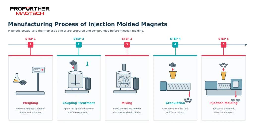 Injection Molded NdFeB Production Flow The injection molded NdFeB production route as a flow diagram. Project-specific tooling and magnetization are confirmed in the quotation.Select the diagram to open the full-resolution file in a new tab.

Magnetization on This Route
Orientation and magnetization are not the same step: orientation is set while the part is formed or compacted, magnetization is applied afterwards, and what a part can take depends on the material, the tooling and the geometry. Describe the direction, the pole pattern and the face the poles have to sit on — or send the part or its drawing and we will read it with you.
Magnetization feasibility depends on the material, manufacturing process, geometry and required pole pattern. Send us your drawing, sample or magnetization diagram for evaluation.
Explore Magnetization Directions & Pole Patterns → · Magnetization directions and pole patterns explained → · Send the drawing or a sample →
Explore the material overview and compare the available manufacturing routes:
Geometries whose own page names this route. A shape that is not listed does not name this route yet, which says the route is not stated for it - not that the geometry cannot be made this way.
Technical notes and selection articles that reference this route.
- How to Specify Magnetization on a Drawing Technical Guide
How to describe magnetization …
Planning a Part on This Route?
Send the drawing, the sample or the operating conditions you work from. We review the route against the part and answer with the tooling, tolerance and feasibility questions it raises.