Sintered NdFeB Ring Magnets for an Encoder Application
Project Starting Point: Application Requirement
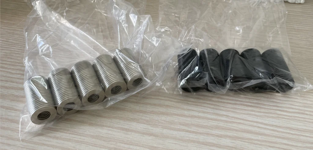
A manufacturing process change helped bring sintered NdFeB ring magnets into line with a customer’s sine–cosine signal requirements for rotor-position sensing.
Project Overview
| Material | Sintered NdFeB |
|---|---|
| Shape | Ring |
| Application | Magnetic encoder for rotor-position sensing |
| Surface Finish | Nickel coating on the validated version |
| Orientation Requirement | Orientation deviation < 1.5°, stated only in a later drawing revision |
| Key Requirement | Sine–cosine signal quality and the customer’s 2.0% eccentricity-error acceptance limit, stated during the investigation rather than on the original drawing |
| Validation Result | A 500-piece revised sample batch and a subsequent 2,000-piece delivery passed customer testing |
Project Background
The customer designs electronic sensors and smart systems for the textile sector. It used nickel-coated sintered NdFeB ring magnets in a magnetic encoder, where four sensors, arranged at 90-degree intervals, measured the magnetic field during rotation. The resulting sine and cosine signals were used to calculate rotor position.
Two early sample deliveries performed correctly. A later production batch, however, produced signal distortion and excessive eccentricity error in the customer’s application tests.
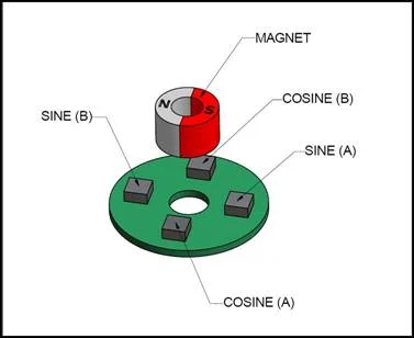
Ring magnets are specified by outside diameter, bore diameter and axial height; the geometry itself is described on ring magnets.
1. The Engineering Challenge
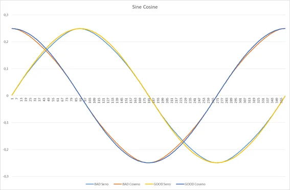
Customer ProblemAccording to the customer's test report, magnets that passed and failed the application test showed similar signal amplitudes. The reported difference was in the sine–cosine waveform shape and the resulting eccentricity error.
Four linear Hall sensors read the field as the magnet turns, producing one sine and one cosine signal, and the drive software derives rotor position from the two signals. That derivation is only as good as the relationship between the two signals: plotted one against the other, a clean pair traces a closed circle, and anything that deforms that circle — eccentricity among it — becomes a position error. The software then drives the motor from an angle it has read slightly wrong.
The failed batch varied part to part rather than shifting as a whole. Some magnets reconstructed a clean circle and passed the application test; others produced a distorted one and failed it. Same drawing, same material, same process route — and nothing in the specification told the production side which of the two outcomes it was shipping.
These findings shifted the investigation beyond magnetizing equipment. ProfurtherMag coordinated the exchange of test reports, sensor-layout information and production feedback to clarify what needed to be controlled.
The 2.0% was not on the original drawing. It came from the customer during the exchanges that followed the failed batch, as a goal for the application: “Our goal is to have Sine-Cosine signals without distortion, the maximum error in eccentricity should be possibly lower than 2.0%.” The clean-circle plot under Acceptance Comparison is the eccentricity limit the customer could accept in that application — a functional acceptance criterion for the sensor system, not a dimensional tolerance for the magnet.
The sensor arrangement also carries an angular requirement. Because the four sensing positions fix where the sine and cosine signals are sampled, a magnet's orientation relative to its own datum is part of the functional specification, not a detail left to production judgement. A ring can sit inside its dimensional tolerance and still shift the electrical angle the sensor reads.
2. Technical Assessment & Root Cause Analysis
InvestigationThe orientation-deviation limit appeared only in a later drawing revision: Orientation deviation < 1.5°. Until it was written down, no delivered batch could be checked against it. The requirement existed only inside the customer's application test, so a batch that failed there could not be traced back to a stated drawing value — and a supplier working from a drawing without it has no reason to depart from its standard process for that geometry.
Once stated, the two requirements were treated as separate items: the orientation limit is measurable in production, while the signal-based acceptance criterion is confirmed by the customer's sensor test.
The production review focused on how the manufacturing process could better support the accuracy required by the application.
3. Actions Executed by ProfurtherMag
ExecutionRather than continuing with the original direct-forming approach, the manufacturing partner adopted a different machining sequence: pressing block blanks, cutting them into rectangular bars, using centerless grinding to produce cylindrical blanks, and then slicing.
This change was intended to improve control of the cut faces relative to the cylinder axis. ProfurtherMag coordinated the revised samples and followed up with the customer's engineering team to obtain application-level feedback.
This sequence was settled between ProfurtherMag and the manufacturing partner, not with the customer. Once the signal requirement was on the table, meeting it left only this route instead of the conventional direct-forming process; the customer's part in the change was the application test that followed.
4. Project Outcome & Serial Results
Recorded ResultA subsequent 2,000-piece delivery was also tested, and the customer confirmed that all pieces passed.
These results validated the revised production approach for this application.
Practical Takeaway
For encoder magnets, material grade and dimensions are only part of the specification. Manufacturing accuracy, magnetic orientation and performance within the sensor arrangement may also need to be defined and verified.
A requirement the customer does not put on the drawing does not reach the production plan. Without it the supplier applies its standard process for that geometry, because the application — the sensor layout, the sampling positions, the angle the signals define — is not visible from the drawing alone. The mismatch then surfaces at the customer's test: one side absorbs rework and re-testing, the other a delayed assembly.
This project reinforced the importance of:
- Understanding the magnet's function within the customer's assembly.
- Stating the orientation-deviation limit on the drawing — here Orientation deviation < 1.5° — together with the sensing arrangement it is measured against, so the supplier can inspect it before shipment.
- Translating application feedback into drawing requirements and production controls.
- Validating a revised process with a meaningful sample batch before further delivery.
ProfurtherMag's role was to keep the customer's engineering requirements and the manufacturing partner's process decisions connected throughout the investigation and validation.
Acceptance Comparison
Test ResultsDistortion — Not Acceptable
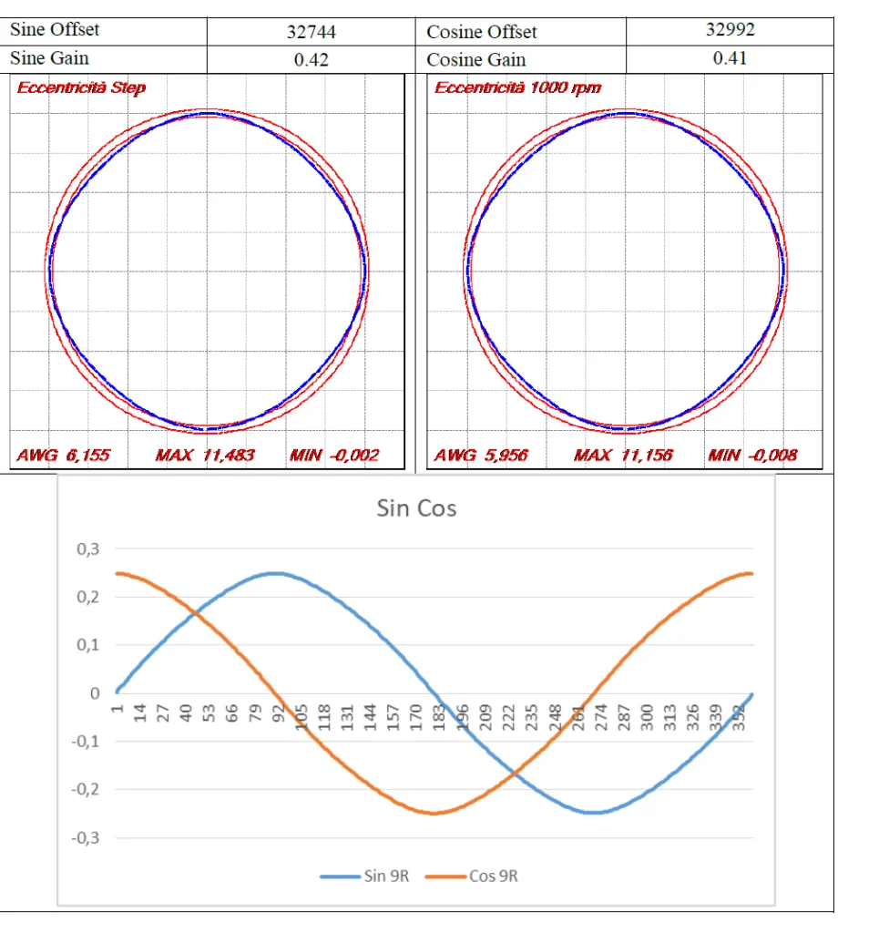
Reconstructed plot deforms away from a circle. Measured on this motor: AWG 5.292 · MAX 10.490 · MIN -0.045 — eccentricity error above the 2.0% limit, not acceptable in the sensor application.
Perfect Circle — Acceptable
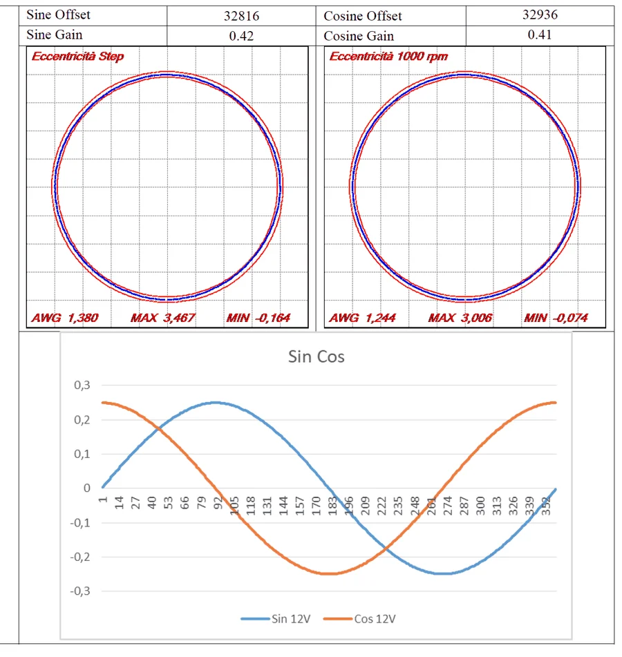
Reconstructed plot closes on a clean circle. Measured on this motor: AWG 0.705 · MAX 1.537 · MIN -0.097 — eccentricity error within the 2.0% limit, acceptable in the sensor application.
Related Records
This project record is filed against the pages below. Each one opens its own record, where the material, application or route is described in full.
Discuss Your Sensor Magnet Project
If you are developing an encoder or rotor-position sensing assembly for textile machinery or another drive application, send us your magnet drawing, magnetization requirements and application test criteria, including any orientation-deviation limit your sensing arrangement requires and the sensor layout it is measured against. An approved reference sample or signal report can also help us review the requirements with the appropriate manufacturing partner.
Reviewed by the ProfurtherMag team.