Dry Pressed Ferrite
Dried ferrite powder compacted in a press. Suits simple rings, blocks and discs in repeat production; alignment is lower than wet pressing.
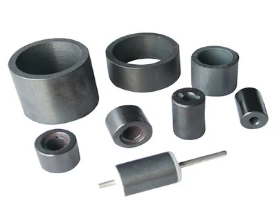
Dry-pressed ferrite is formed by compacting dry ferrite powder, followed by sintering and any required finishing. Isotropic and anisotropic grades are evaluated according to the material and tooling; anisotropic production uses an orienting magnetic field. The route is often considered for simple geometries and cost-sensitive repeat production.
Wet pressing and dry pressing work the same strontium ferrite system, and the difference is the moisture at forming: wet pressing compacts a slurry at 30–40 % water content and drains that water during pressing, whereas dry pressing dries the same slurry first and compacts powder below 10 % moisture. Sintering and finishing are then essentially the same step on both routes. The wet-pressed route page sets the two side by side.
How the part is formed
- The slurry is dried first, so the press receives free-flowing powder below 10 % moisture instead of a wet compact.
- The die is filled and the powder compacted in one stroke, in the shape the tool was cut for; anisotropic grades are compacted in an orienting field.
- Sintering follows, then the finishing the drawing calls for — grinding, or none at all.
- Sintered ferrite is normally supplied uncoated; compatibility with the actual fluid or chemical exposure is checked for the application.
Where a part needs more flux per unit volume than this alignment gives, the same drawing is reviewed against wet pressed ferrite, or against a different material system, before a route is fixed.
Core Process Characteristics
The material this route works in, the advantage that decides it, the limitation to plan around, and the parts it is normally specified for.
| Primary Material | Hard Ferrite (Ceramic) Magnets |
|---|---|
| Core Advantage |
|
| Key Limitation |
|
| Typical Applications |
|
Process Characteristics
The parameters recorded for this route, each with the note that says how it is confirmed on a project.
| Primary Material | Strontium Hard Ferrite (SrO·6Fe2O3) The same strontium ferrite system as the other ferrite routes. |
|---|---|
| Forming Method | Dry powder compaction in mechanical or hydraulic presses The die is cut for the part family; simple geometry is what keeps the route economical. |
| Forming Moisture | Dried powder, below 10 % moisture This is the substantive difference between dry and wet pressing. Wet pressing compacts a slurry at 30–40 % water content and drains the water during pressing; the sintering and finishing steps that follow are essentially the same. |
| Magnetic Orientation | Anisotropic or isotropic, depending on grade Anisotropic grades perform higher than isotropic, so the orientation direction is defined with the magnet design. |
| Magnetization Options | Matched to grade, forming orientation and geometry A magnetization pattern is a project requirement, not a standard menu item; it is matched to the grade, the forming orientation, the geometry and the magnetizing fixture. |
| Magnetic Performance | Br 380–460 mT, (BH)max 27.0–41.8 kJ/m³ across the listed sintered grades That band belongs to the material line, not to this route as a guarantee. Alignment here is lower than wet pressing, so a part specified at the top of the band is reviewed on the wet-pressed route before the drawing is fixed. Compare the grade data rather than the route name. |
| Tooling & Cycle | Lower tooling and faster cycles than wet pressing Tooling cost and cycle are assessed against the geometry and the volume; dry pressing is the economical route for suitable simple parts. |
| Typical Shapes | Ring, block, disc Simple geometries where this route is economical. |
| Surface Treatment | Normally uncoated Special surface treatment is evaluated against the mounting, bonding, appearance and environmental requirements of the assembly. |
| Sintered Density & Curie Temperature | 4.5–5.1 g/cm³; θc 460–480 °C Listed physical properties of the sintered ferrite grades. They hold for dry- and wet-pressed parts alike, because sintering is the same step on both routes — which is also why the two routes are separated by forming, not by the finished material. |
| Temperature Behaviour | αBr −0.2 %/K; αHcJ 0.2–0.5 %/K, both quoted for 0–100 °C Remanence drops about 0.2 % per kelvin above room temperature, so a flux margin that only just closes at 20 °C will not close in a warm housing. The coercivity coefficient is positive, which puts the weakest coercivity at the cold end — that is the temperature where the demagnetizing field is checked. |
Technical Documents
-
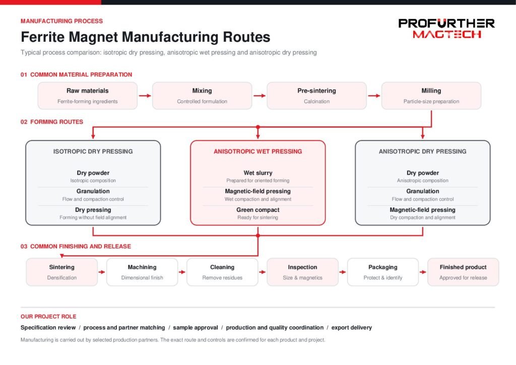 Ferrite Magnet Manufacturing Routes — Wet Pressed & Dry Pressed (PDF) Dry pressing and wet pressing are drawn side by side, step by step from raw material through sintering and finishing to magnetized parts, so the two routes can be compared on the same terms before one is fixed for a part: what each forming step costs, and what each route leaves to be machined or finished. Injection molded ferrite is a separate route and is not part of this comparison.Select the preview to open the document in a new tab.
Magnetization on This Route
Orientation and magnetization are not the same step: orientation is set while the part is formed or compacted, magnetization is applied afterwards, and what a part can take depends on the material, the tooling and the geometry. Describe the direction, the pole pattern and the face the poles have to sit on — or send the part or its drawing and we will read it with you.
Magnetization feasibility depends on the material, manufacturing process, geometry and required pole pattern. Send us your drawing, sample or magnetization diagram for evaluation.
Explore Magnetization Directions & Pole Patterns → · Magnetization directions and pole patterns explained → · Send the drawing or a sample →
This manufacturing route is worked in the following material line:
Geometries whose own page names this route. A shape that is not listed does not name this route yet, which says the route is not stated for it - not that the geometry cannot be made this way.
Technical notes and selection articles that reference this route.
- How to Specify Magnetization on a Drawing Technical Guide
How to describe magnetization …
Planning a Part on This Route?
Send the drawing, the sample or the operating conditions you work from. We review the route against the part and answer with the tooling, tolerance and feasibility questions it raises.