Sintered NdFeB
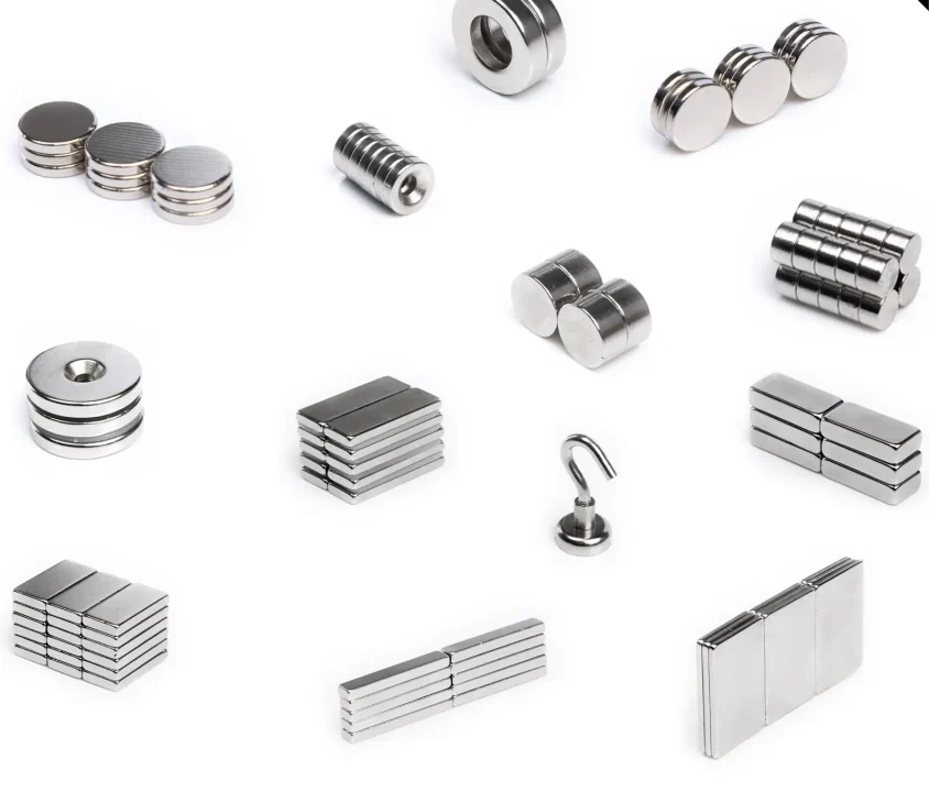
NdFeB strip cast, milled, pressed in a field, sintered and heat treated. Rings, discs, blocks and arcs; the parts are brittle, so handling needs care.
Sintered NdFeB starts with alloy melting and strip casting. Hydrogen decrepitation breaks the alloy into coarse particles, followed by fine milling. The powder is aligned in a magnetic field and pressed, then sintered and heat treated. The sintered material is subsequently machined to the drawing, with surface protection and magnetization specified for the application.
How the part is formed
- Melting and strip casting fix the alloy composition and the grain structure before any powder exists.
- Hydrogen decrepitation and fine milling break the strip down to single-crystal particles; milling under nitrogen keeps oxygen out of a material that corrodes readily.
- The powder is aligned in a magnetic field while it is pressed, which is where the anisotropy — and most of the grade's Br — is set.
- Sintering and heat treatment densify the compact and build the coercivity; the part is then machined to the drawing, because a sintered blank is ground to tolerance rather than molded to it.
- Surface protection and magnetization come last, and both are specified for the application rather than assumed.
Industrial servo motors, EV traction motors, linear actuators and high-torque robotic joints are the duties this route is specified for; the application guidance sits in Electric Motors & Drives and Industrial Equipment & Couplings. Coating options for this route are listed in the coating options table.
Core Process Characteristics
The material this route works in, the advantage that decides it, the limitation to plan around, and the parts it is normally specified for.
| Primary Material | Neodymium (NdFeB) Rare Earth Magnets |
|---|---|
| Core Advantage |
|
| Key Limitation |
|
| Typical Applications |
|
Process Characteristics
The parameters recorded for this route, each with the note that says how it is confirmed on a project.
| Material System | Neodymium-Iron-Boron (NdFeB) Rare-earth permanent magnet material; the grade is fixed with the project. |
|---|---|
| Manufacturing Route | Strip casting to sintered, machined part Alloy melting and strip casting → hydrogen decrepitation → fine milling under nitrogen → magnetic field alignment and pressing → sintering and heat treatment → machining → surface protection and magnetization as specified. |
| Relative Performance | Highest of the three routes — Br 1170–1470 mT in the N series, 1020–1470 mT across N to AH Sintered NdFeB performs above bonded NdFeB and above ferrite. The higher-coercivity series trade a little Br for temperature capability, which is why the top of the Br band sits in the N series. |
| Energy Product | (BH)max 263–446 kJ/m³ (33–56 MGOe) in the N series Taken from the sintered grade tables on the material page: N35 at 263–287 kJ/m³ up to N55 at 422–446 kJ/m³, with the M, H, SH, UH, EH and AH series sitting in a similar band on progressively lower Br. The grade sets the ceiling; the magnetic circuit sets the operating point the part actually works at. |
| Max Operating Temperature | 80 °C (N) to 230 °C (AH) across the series The series value is the grade's maximum operating temperature; the working point and the magnetic circuit decide what the part can take, not the ambient figure. N grades are quoted at 80 °C and M at 100 °C, and the ceiling climbs through H, SH, UH and EH to AH as coercivity is bought with Br. Confirmed per grade and application. |
| Surface Protection | Selected for the environment — zinc or nickel at 4–20 µm, epoxy at 15–65 µm Refer to the sintered NdFeB coating table for the finishes; the final coating structure and acceptance criteria are confirmed for the project. Salt-spray duration and adhesion are agreed separately and are not implied by the thickness figures. |
| Common Forms | Ring, disc, block, strip, arc segment, countersunk Multipole rings are evaluated per project against the tooling and the magnetizing fixture. |
| Mechanical & Physical | Density 7.40–7.80 g/cm³; Vickers 550–650 HV; compressive strength 1050 MPa; bending strength 290 MPa Reference values from the physical properties table on the material page, not batch results. The hardness and the brittleness are the reason a sintered blank is ground to tolerance rather than cut, and the reason handling and clamping in the assembly have to be designed around it. |
Manufacturing Route Diagram
-
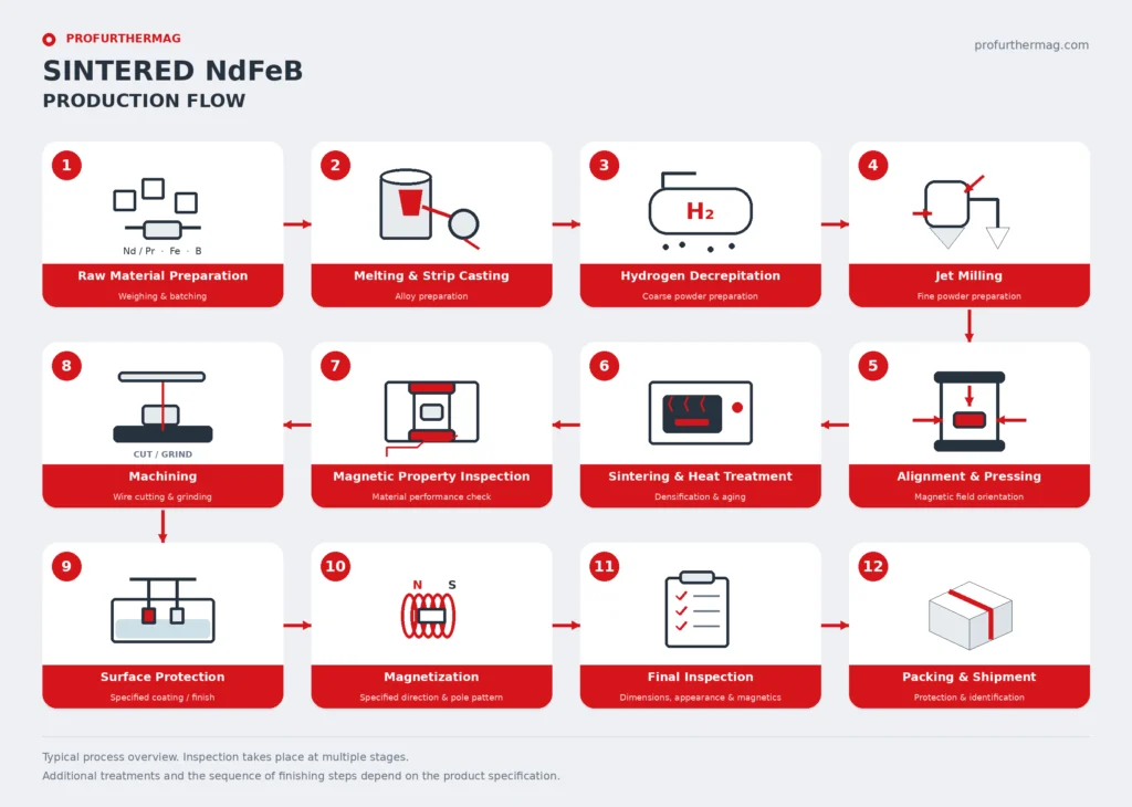 Sintered NdFeB Production Flow The sintered NdFeB production route as a flow diagram. Project-specific inspection points are confirmed in the quotation.Select the diagram to open the full-resolution file in a new tab.

Magnetization on This Route
Orientation and magnetization are not the same step: orientation is set while the part is formed or compacted, magnetization is applied afterwards, and what a part can take depends on the material, the tooling and the geometry. Describe the direction, the pole pattern and the face the poles have to sit on — or send the part or its drawing and we will read it with you.
Magnetization feasibility depends on the material, manufacturing process, geometry and required pole pattern. Send us your drawing, sample or magnetization diagram for evaluation.
Explore Magnetization Directions & Pole Patterns → · Magnetization directions and pole patterns explained → · Send the drawing or a sample →
Explore the material overview and compare the available manufacturing routes:
Geometries whose own page names this route. A shape that is not listed does not name this route yet, which says the route is not stated for it - not that the geometry cannot be made this way.
View sintered NdFeB magnetic properties, physical properties, coating references and the sintered NdFeB datasheets (PDF).
Technical notes and selection articles that reference this route.
- Ferrite vs. NdFeB: Motor Selection Guide Technical Guide
When to pick hard ferrite over…
- Magnet Tolerances, Grinding and Plating Technical Guide
How critical tolerances are re…
- How to Specify Magnetization on a Drawing Technical Guide
How to describe magnetization …
Planning a Part on This Route?
Send the drawing, the sample or the operating conditions you work from. We review the route against the part and answer with the tooling, tolerance and feasibility questions it raises.