Wet Pressed Ferrite
Ferrite slurry compacted in an orienting field and drained during pressing. The route for parts that need more flux per unit volume than dry pressing.
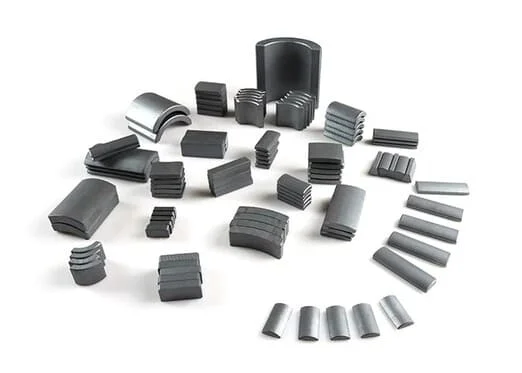
Strontium ferrite powder is carried in a slurry and compacted in the die under a strong orienting magnetic field, with the water drained from the compact during pressing. Because the particles stay aligned while the part forms, the crystalline alignment is tight, and this is the route we assess when a part needs more flux per unit volume than the dry-pressed route can give in the same envelope. Grade-led figures are read against the evidence for the specific material, grade and process, not against a general ferrite figure.
The route diagram published on this page shows wet pressing and dry pressing side by side, from raw material through sintering and finishing to the magnetized part, and the comparison below follows the same steps. Injection molded ferrite is not part of this comparison.
When wet pressing is worth evaluating
- The design is limited by flux per unit volume rather than by part price.
- The alignment direction is designed into the magnetic circuit, as it is in motor arc segments.
- A multipole or radial-oriented pattern is being considered on a ring or an arc segment form; the pattern must be compatible with the forming orientation and is confirmed per project.
- The grade can be fixed early, because our ferrite work is strontium based and the judgement is made on the specific grade.
Wet pressing against the dry-pressed route
These are general process tendencies. Actual performance, tooling cost, cycle time and finishing requirements depend on the grade, geometry, equipment and production volume. Both routes compact the same strontium ferrite system in a die, and the difference starts at forming: wet pressing compacts a slurry at 30–40 % water content and drains that water during pressing, while dry pressing compacts dried powder below 10 % moisture. Sintering and finishing are essentially the same step on both routes, so the five differences below are what follows from the forming moisture. None of them carries a published figure: tooling, MOQ, price, lead time and sample fee are quoted per project from the drawing and the quantity.
| What is compared | Wet pressed ferrite | Dry pressed ferrite |
|---|---|---|
| Forming moisture | A slurry carried at 30–40 % water content; the water is drained from the compact during pressing. | The slurry is dried first, and powder below 10 % moisture is compacted in the press. |
| Orientation and performance | Slurry compaction in a strong orienting field. The higher alignment it produces is why the route is assessed when flux per unit volume is the constraint; its figures are argued from the material, grade and process evidence of the part. | Dry compaction of the same system. Achievable alignment is lower, so flux per unit volume is lower, and moderate-flux parts are normally specified here. |
| Achievable shapes | Arc segments, rings, blocks and discs. Long arcs, rings and thin sections are the shapes that bring wet pressing into the discussion; suitability is assessed per structure. | Simple rings, blocks and discs, in simple geometry and repeat production. |
| Tooling | Precision slurry drainage tooling, drawn for the part and quoted with it. It is the first cost a project carries. | Tooling quoted per project; it is what keeps the route economical for standard geometries. |
| Machining and finishing | Pressed close to the drawing. What is left to machine or finish after pressing follows the structure and the tolerance callouts, and is confirmed per drawing rather than promised away. | The same principle: the work left after pressing follows the drawing and the tolerance, and is confirmed per part. |
| Production economics | Slower cycle and higher tooling, so the route is justified by the performance need or by the annual quantity rather than by unit price alone. | Rapid cycles and lower tooling, which suit repeat production of standard geometries and cost-sensitive assemblies. |
Tooling, sample charges, MOQ, lead time and delivery terms are confirmed in the project quotation. See Commercial & Delivery for the general commercial framework.
Limits of the wet pressing process
These belong to the process itself and apply to every wet pressed part, arc segment or not.
- The tooling is part-specific. Slurry drainage tooling is made for one part family, and that investment lands before any good part is produced. Weigh it against the quantity you expect to run and the performance the part needs, because it is quoted from the drawing and not from a list.
- Slower cycle. Pressing takes longer per part than the dry route, which moves unit cost at volume and the time to a first batch into the project conversation instead of onto the page.
- Size and structure. Some large sizes, thin sections and open structures are not suitable for pressing. Sending the drawing early gets that answer before tooling is discussed, because it is answered per structure.
- Machining allowance. Plan for the finishing work to be confirmed from the drawing and the tolerance callouts. No magnet route lets us promise a part that needs no post-machining.
- Performance and temperature. A higher Hcj does not follow from the route name; it is compared against the specific material, grade and process evidence. Operating temperature is fixed per grade and per part rather than as one figure for ferrite.
Limits that come from assembling arc segments
These apply to arc segment designs, not to the process. A ring, block or disc is pressed as one part and carries only the process limits above.
- Separate arc segments require individual positioning and retention in the assembly. Bonding or fixing, fixtures and consistency checks contribute to the total assembly cost; pressing productivity depends on the tooling and equipment.
- Segment position, gap and balance are set by the customer's assembly design and fixtures. We coordinate the magnet drawings with the assembly, and the checks that close the assembly are agreed per project.
- If a drawing can be pressed as one ring but is specified as segments, that is a cost decision worth taking at the start: the two structures differ in tooling and in assembly work, and the structure choice stays with the customer.
What to confirm before a wet pressing quote
A preliminary material and process judgement and a first-round substitution feasibility assessment are made from the drawing or the sample, and they are coordinated between the partner-factory engineers and yours. The conditions that decide the answer:
- Drawing or sample, with the dimensions and tolerances that matter.
- The flux, Br and Hcj the design needs, and the grade or evidence they come from.
- Magnetization pattern: axial, diametrical, multipole or radial-oriented multipole.
- Operating temperature and environment, and whether the assembly calls for a coating.
- Structure: a single ring, or a set of arc segments, and how the magnet is fixed in the assembly.
- Annual quantity and delivery term.
How the work is run
ProfurtherMag is not a magnet factory: production runs in partner factories, while ProfurtherMag owns the requirements, the technical coordination, the factory matching, sampling, production follow-up, export and after-sales. Factory outgoing inspection is the base for the shipment; on top of it we add a risk-based review, on site or by a third party, at a level set by the project's risk rather than a visit on every batch.
Core Process Characteristics
The material this route works in, the advantage that decides it, the limitation to plan around, and the parts it is normally specified for.
| Primary Material | Hard Ferrite (Ceramic) Magnets |
|---|---|
| Core Advantage |
|
| Key Limitation |
|
| Typical Applications |
|
Process Characteristics
The parameters recorded for this route, each with the note that says how it is confirmed on a project.
| Primary Material | Strontium Hard Ferrite (SrO·6Fe2O3) Strontium is the ferrite system we work in; barium ferrite is not normally quoted. The grade is fixed with the project. |
|---|---|
| Forming Method | Wet compaction of ferrite slurry, drained during pressing Sintering and the finishing the drawing calls for follow the pressing step. Whether a given part shape can be pressed is judged from the drawing. |
| Forming Moisture | 30–40 % water content, drained during pressing This is the substantive difference between wet and dry pressing. Dry pressing dries the same slurry first and compacts powder below 10 % moisture; the sintering and finishing steps that follow are essentially the same. |
| Magnetic Orientation | Anisotropic The pressing field sets the alignment direction, and that direction is agreed with the magnet design rather than assumed. |
| Magnetic Performance | Br 380–460 mT, (BH)max 27.0–41.8 kJ/m³ across the listed sintered grades The band belongs to the material line; where inside it a part lands follows the specified grade. Wet pressing produces the tighter particle alignment of the two pressing routes, which is why a drawing that needs the top of the band is assessed here rather than on the dry route. Br, HcB, HcJ and (BH)max remain grade figures, and a higher HcJ does not follow from the forming route alone. |
| Sintered Density & Curie Temperature | 4.5–5.1 g/cm³; θc 460–480 °C Listed physical properties of the sintered ferrite grades. They hold for wet- and dry-pressed parts alike, because sintering is the same step on both routes — the two routes are separated by forming, not by the finished material. |
| Temperature Behaviour | αBr −0.2 %/K; αHcJ 0.2–0.5 %/K, both quoted for 0–100 °C Remanence drops about 0.2 % per kelvin above room temperature, so a flux margin that only just closes at 20 °C will not close in a warm housing. The coercivity coefficient is positive, which puts the weakest coercivity at the cold end — that is the temperature where the demagnetizing field is checked. |
| Typical Shapes | Arc segment, ring, block, disc Shape is a project technical attribute rather than a business classification; large sizes and thin sections are assessed per structure. |
| Magnetization Options | Axial, diametrical, multipole, radial-oriented multipole The pattern must be compatible with the forming orientation and is confirmed per project against the magnetizing fixture and the assembled part. |
| Surface Treatment | Coating only where the exposure calls for it Hard ferrite is a ceramic oxide, so a coating step is added where the exposure calls for it rather than as standard; confirmed per project. |
Technical Documents
-
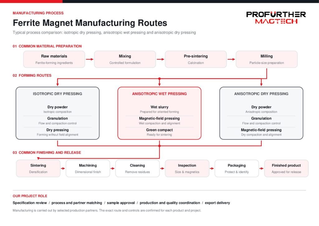 Ferrite Magnet Manufacturing Routes — Wet Pressed & Dry Pressed (PDF) Wet pressing and dry pressing are drawn side by side, step by step from raw material through sintering and finishing to magnetized parts, so the two routes can be compared on the same terms before one is fixed for a part: what each forming step costs, and what each route leaves to be machined or finished. Injection molded ferrite is a separate route and is not part of this comparison.Select the preview to open the document in a new tab.
Magnetization on This Route
Orientation and magnetization are not the same step: orientation is set while the part is formed or compacted, magnetization is applied afterwards, and what a part can take depends on the material, the tooling and the geometry. Describe the direction, the pole pattern and the face the poles have to sit on — or send the part or its drawing and we will read it with you.
Magnetization feasibility depends on the material, manufacturing process, geometry and required pole pattern. Send us your drawing, sample or magnetization diagram for evaluation.
Explore Magnetization Directions & Pole Patterns → · Magnetization directions and pole patterns explained → · Send the drawing or a sample →
This manufacturing route is worked in the following material line:
Geometries whose own page names this route. A shape that is not listed does not name this route yet, which says the route is not stated for it - not that the geometry cannot be made this way.
Documented project records delivered through this manufacturing route.
- Ferrite Arc Magnets for Water Pump Yokes Delivered Project
An arc segment for a water pur…
Technical notes and selection articles that reference this route.
- Ferrite vs. NdFeB: Motor Selection Guide Technical Guide
When to pick hard ferrite over…
- Magnet Tolerances, Grinding and Plating Technical Guide
How critical tolerances are re…
- How to Specify Magnetization on a Drawing Technical Guide
How to describe magnetization …
- Only Have a Sample? How to Start an Inquiry Buying / Sourcing Guide
No drawing, grade or magnetiza…
Planning a Part on This Route?
Send the drawing, the sample or the operating conditions you work from. We review the route against the part and answer with the tooling, tolerance and feasibility questions it raises.